
Turbocharger control linkage with reduced heat flow
a technology of control linkage and heat flow, which is applied in the direction of machines/engines, combination engines, liquid fuel engines, etc., can solve the problems of premature wear-out of the ball joints in the rod end, and achieve the effects of increasing the stiffness of the control linkage shaft, reducing vibration, and increasing cost-effectiveness
Patent Information
- Authority / Receiving Office
- US · United States
- Patent Type
- Patents(United States)
- Current Assignee / Owner
- Publication Date
- 2016-09-06
- Estimated Expiration
- Not applicable · inactive patent
Smart Images
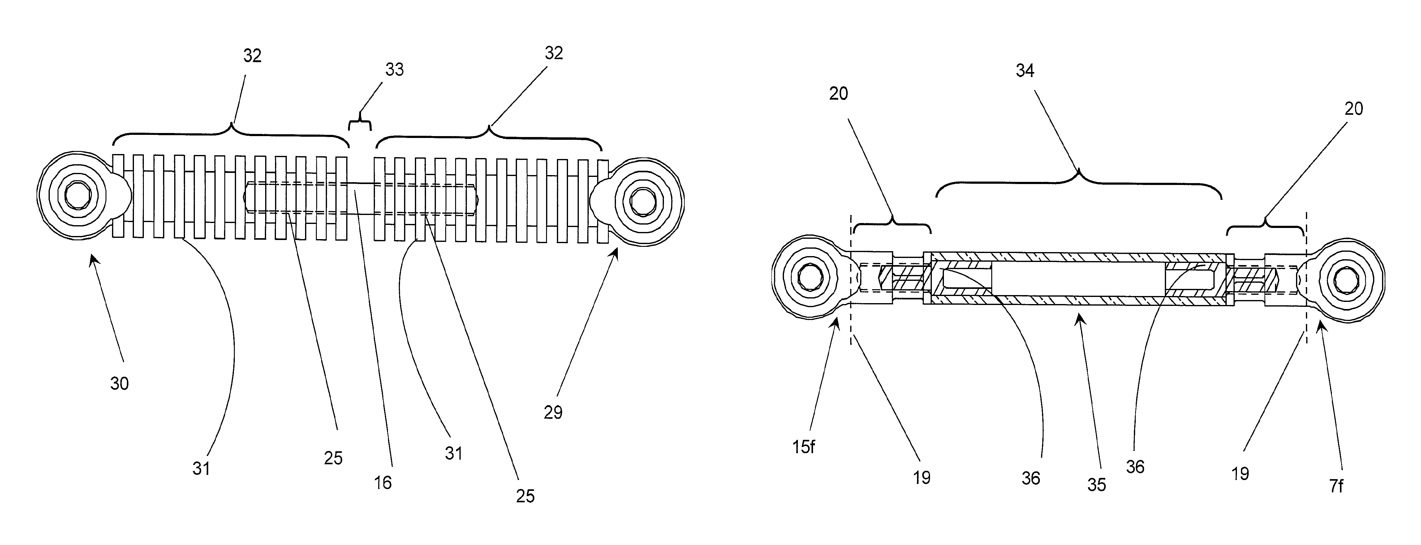
Figure 1 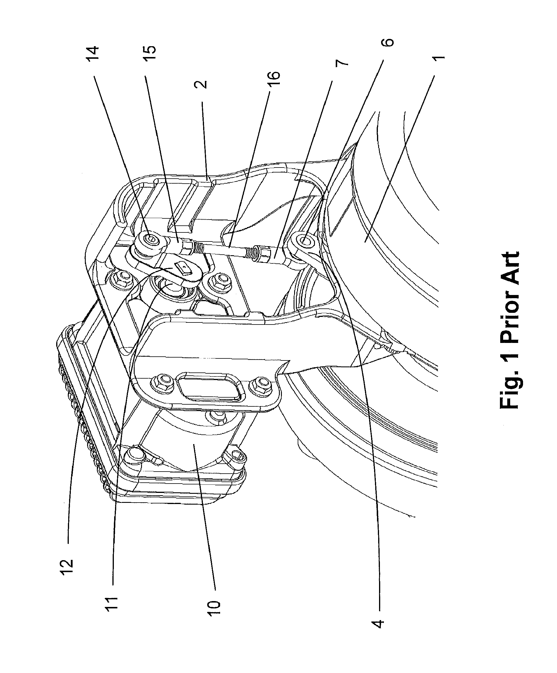
Figure 2 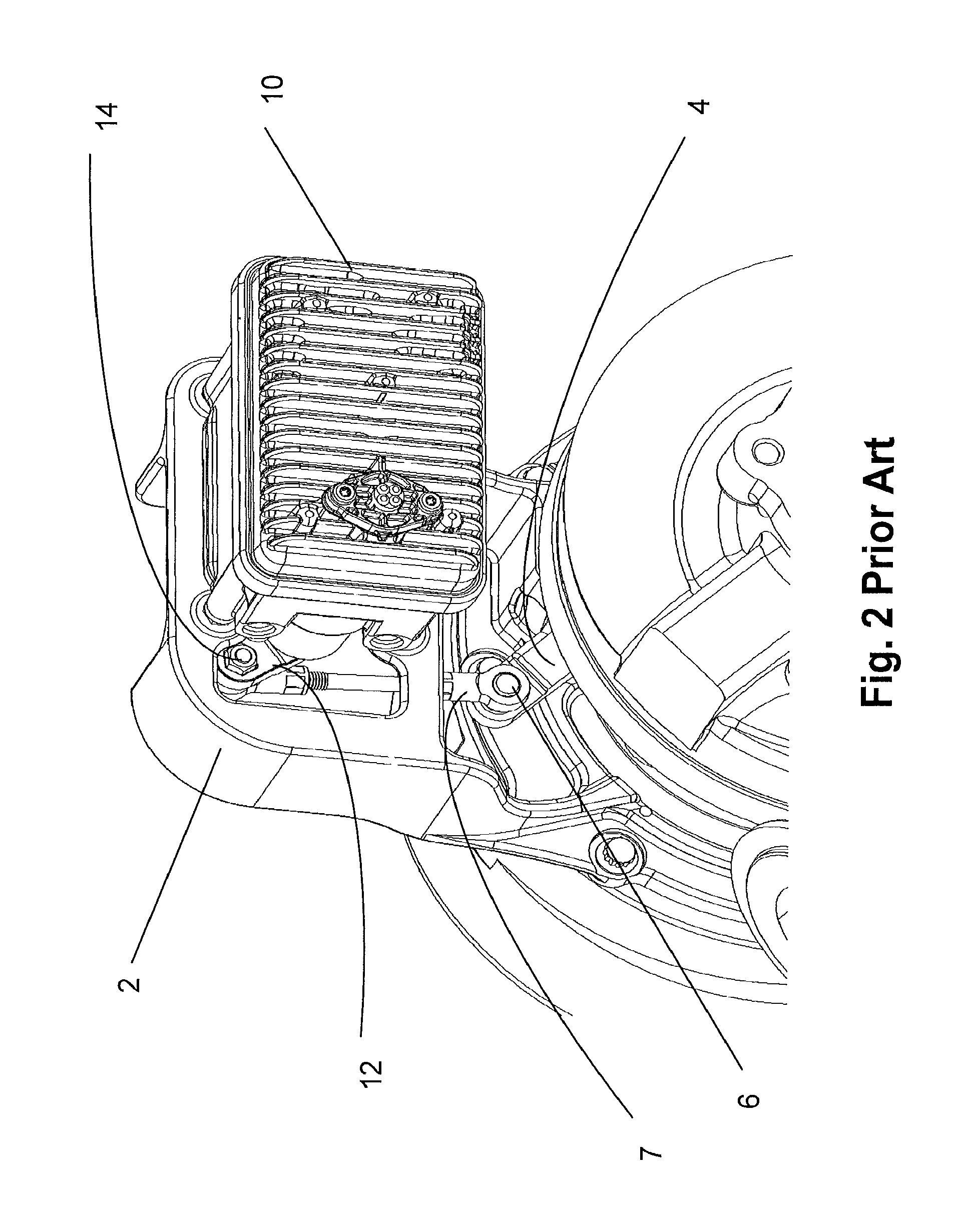
Figure 3
Abstract
Description
FIELD OF THE INVENTION
[0001] The invention is directed to a Variable Turbine Geometry (VTG) turbocharger with an electric motor driven actuator, or a wastegated turbocharger, and in particular, the design of a wastegate or VTG electronic actuator unit.BACKGROUND OF THE INVENTION
[0002] Turbochargers are a type of forced induction system for internal combustion engines which use the exhaust flow, entering the turbine housing from the engine exhaust manifold, to drive a turbine wheel, which is located in the turbine housing. To control the energy to the turbine wheel, and thus the boost output of the turbocharger, which, in turn, affects the power output of the engine, a variable geometry configuration of the turbine stage is used to control said turbine energy. In the case of a VTG, an actuator is used to control the turbine power.
[0003] While the highest exhaust temperature of a gasoline engine is up to 1050° C., the exhaust temperature of a large Diesel engine is typically up to 760° C...
Examples
example 1
Calculating Effective Heat Radiating Surface Area of a Conventional Control Linkage
[0048]This Example will serve to demonstrate how to calculate the effective heat radiating surface area of a conventional control linkage. The control linkage of Example 1 has a conventional design, and because it has the same two critical reference dimensions as the following inventive examples, i.e., (a) centerline length 111.56 mm and (b) bore diameter 6 mm, it will also be the “baseline” against which the inventive control linkages (Examples 2-5) will be compared.
[0049]As can be seen from FIGS. 4 and 6, the female rod end (7f) is comprised of two main sections: (a) the cylindrical zone (20), or barrel, of the rod end, which houses the threaded bore (25), and (b) the head, which has a generally circular outer diameter and houses the ball (8). The ball is mounted in the head for rotation and swivel and has a bore (9) into which the drive pin or driven pin (6, 14) is inserted.
[0050]The head section (...
example 2
Calculating Surface Area of Control Linkage with Radial Fins on Rod Ends
[0067]In an embodiment having the inventive rod end (30), as depicted in FIG. 5, the substantially cylindrical outer surface zone (20) of the rod-end (7f), as depicted in FIG. 4, is substituted by a surface which encompasses a plurality of cooling fins (31). The centerline length remains 111.56 mm in the Examples to correspond to the “baseline” control linkage of Example 1. In general the plurality of cooling fins may be provided along at least one axial segment of said control linkage, or may extend along the entire axial length of the substantially cylindrical outer surface zone (32) of the rod-end (30). The cooling fins extend radially outwardly generally perpendicular to the axis of the control linkage, are axially spaced, and generally annular, whereby the effective surface of the control linkage is increased. For a typical 6 mm rod-end, the length of the substantially cylindrical section is lengthened acco...
example 3
Calculating Surface Area of Control Linkage with Hollow Shaft
[0074]In a second embodiment of the control linkage of the invention, as depicted in FIG. 8, the reduction in heat transfer and / or increase in heat radiation is accomplished by using a hollow tubular center section instead of the conventional solid shaft. End couplers (36) are fixed to each end of a hollow substantially cylindrical tube (35) to enable standard female rod-ends (70 to be mounted on threaded male protrusions (39) of the end couplers (36). In this embodiment the surface area of the tube is preferably nearly double that of the shaft, i.e., the outer diameter of the tube in example 3 is the same diameter as the substantially cylindrical barrel of the baseline rod-end which is 11 mm (compare FIGS. 6 and 8).
[0075]From a heat conduction standpoint, since the heat conduction of a body is a function of the mass of material in the body, and the length of a solid shaft and the length of a tube are substantially the sam...