How to Reinforce PCB Layouts for Coil Whine Reduction?
AUG 13, 20259 MIN READ
Generate Your Research Report Instantly with AI Agent
Patsnap Eureka helps you evaluate technical feasibility & market potential.
PCB Coil Whine Background and Objectives
Coil whine is a persistent challenge in the electronics industry, particularly in printed circuit board (PCB) design. This high-frequency noise, typically ranging from 1 kHz to 20 kHz, is caused by electromagnetic forces acting on components, primarily inductors and transformers. As electronic devices become more compact and powerful, the issue of coil whine has gained prominence, affecting user experience and product quality across various sectors, from consumer electronics to industrial equipment.
The evolution of PCB technology has been marked by continuous efforts to improve performance, reduce size, and enhance reliability. However, these advancements have inadvertently contributed to the prevalence of coil whine. As circuit densities increase and power requirements grow, the potential for electromagnetic interactions that lead to audible vibrations has also risen. This has necessitated a renewed focus on mitigating coil whine through innovative PCB layout techniques.
The primary objective of reinforcing PCB layouts for coil whine reduction is to minimize the mechanical vibrations that cause the audible noise. This involves a multifaceted approach that considers both the electrical and mechanical aspects of PCB design. By addressing these factors, manufacturers aim to produce quieter, more efficient, and higher-quality electronic devices that meet the increasingly stringent demands of modern consumers and industrial applications.
Key technical goals in this domain include developing layout strategies that dampen vibrations, optimizing component placement to reduce electromagnetic interference, and implementing novel materials and structures that absorb or redirect vibrational energy. Additionally, there is a focus on creating design methodologies that can predict and mitigate coil whine during the early stages of PCB development, potentially saving time and resources in the production process.
The pursuit of effective coil whine reduction techniques is driven by several factors. These include the growing market demand for silent computing and consumer electronics, stricter regulatory standards for electromagnetic compatibility, and the need for reliable operation in sensitive environments such as healthcare and aerospace. As such, advancements in this field have the potential to impact a wide range of industries and applications, from personal computers and smartphones to medical devices and automotive systems.
Understanding the background and setting clear objectives for coil whine reduction in PCB layouts is crucial for guiding research and development efforts. It provides a foundation for exploring innovative solutions that can address this persistent challenge in electronic design, ultimately leading to improved product performance and user satisfaction across the electronics industry.
Market Demand for Quiet Electronics
The demand for quiet electronics has been steadily increasing in recent years, driven by consumer preferences for more comfortable and less intrusive devices. This trend is particularly evident in the personal computing, home entertainment, and office equipment sectors. Users are becoming increasingly sensitive to noise pollution in their living and working environments, leading to a growing market for products that minimize or eliminate coil whine and other electronic noises.
In the personal computing segment, high-performance laptops and desktop computers are under scrutiny for their noise levels. Gamers and professionals who use powerful graphics cards and processors are especially concerned about coil whine, as it can be particularly noticeable during intense computational tasks. This has led to a surge in demand for quieter gaming PCs and workstations, with manufacturers focusing on noise reduction as a key selling point.
The home entertainment sector has also seen a shift towards quieter devices. Smart TVs, audio systems, and streaming devices are expected to operate silently, enhancing the viewing and listening experience. Consumers are willing to pay a premium for products that offer high performance without the distraction of electronic noise, pushing manufacturers to invest in noise reduction technologies.
Office equipment manufacturers are responding to the demand for quieter work environments. Printers, copiers, and other office machines are being redesigned to minimize noise output, including the reduction of coil whine. This trend is driven by the need for concentration in open office layouts and the increasing prevalence of video conferencing, where background noise can be disruptive.
The automotive industry is another significant market for quiet electronics. As electric vehicles gain popularity, the absence of engine noise makes electronic whine more noticeable. Car manufacturers are investing heavily in noise reduction techniques for their onboard electronics to maintain a quiet and luxurious cabin environment.
Consumer electronics companies are recognizing the market potential of quiet devices and are incorporating noise reduction features into their product development cycles. This has led to the emergence of specialized acoustic engineering teams within these organizations, focused on minimizing electronic noise, including coil whine.
The demand for quiet electronics is not limited to consumer products. Industrial and medical equipment manufacturers are also facing pressure to reduce noise levels in their devices. In healthcare settings, for instance, quiet equipment contributes to a more comfortable environment for patients and helps medical professionals perform their duties without distraction.
As awareness of the health impacts of noise pollution grows, regulatory bodies are beginning to implement stricter noise emission standards for electronic devices. This regulatory pressure is further driving the market demand for quiet electronics and pushing manufacturers to innovate in PCB design and component selection to meet these standards.
Current PCB Layout Challenges and Limitations
PCB layout design for coil whine reduction faces several significant challenges and limitations in the current technological landscape. One of the primary obstacles is the increasing complexity of modern electronic devices, which demand higher component density and multi-layer PCB designs. This complexity makes it difficult to isolate and mitigate coil whine sources effectively.
The miniaturization trend in electronics further exacerbates the problem, as designers must work with limited space to implement noise reduction techniques. This constraint often leads to compromises in component placement and routing, potentially increasing the risk of coil whine.
Another challenge lies in the diverse nature of coil whine sources. Different components, such as inductors, transformers, and capacitors, can contribute to coil whine, each requiring specific mitigation strategies. This diversity makes it challenging to develop a one-size-fits-all approach to PCB layout for coil whine reduction.
The high-frequency switching in modern power supplies and digital circuits also poses a significant challenge. These rapid transitions can induce electromagnetic interference (EMI) and vibrations in nearby components, contributing to coil whine. Traditional PCB layout techniques may not be sufficient to address these high-frequency issues effectively.
Furthermore, the interaction between different components and their electromagnetic fields adds another layer of complexity to PCB layout design. Mutual inductance and capacitive coupling between traces and components can lead to unexpected coil whine issues, which are difficult to predict and mitigate through conventional layout techniques.
The limitations of current PCB materials also present challenges in coil whine reduction. While advanced materials with better damping properties exist, their cost and availability often restrict their widespread use in consumer electronics, forcing designers to work with less optimal substrates.
Additionally, the lack of standardized testing and measurement protocols for coil whine makes it challenging to evaluate the effectiveness of different PCB layout strategies consistently. This absence of standardization hampers the development and validation of new coil whine reduction techniques.
The trade-offs between coil whine reduction and other design priorities, such as thermal management and signal integrity, further complicate the PCB layout process. Designers must balance these competing requirements, often leading to compromises that may not fully address the coil whine issue.
Lastly, the time and cost constraints in product development cycles limit the ability to iterate and optimize PCB layouts for coil whine reduction. Designers often face pressure to meet tight deadlines, which can result in suboptimal solutions being implemented in final products.
Existing PCB Layout Reinforcement Techniques
01 PCB layout optimization for coil whine reduction
Optimizing PCB layouts to minimize coil whine by carefully arranging components, traces, and power planes. This includes strategic placement of inductors and capacitors, as well as implementing proper grounding techniques to reduce electromagnetic interference and vibrations that contribute to coil whine.- PCB layout optimization for coil whine reduction: Optimizing PCB layouts to minimize coil whine involves strategic placement of components, careful routing of traces, and implementation of shielding techniques. This approach focuses on reducing electromagnetic interference and vibrations that contribute to coil whine, resulting in quieter and more efficient electronic devices.
- Electromagnetic shielding in PCB design: Incorporating electromagnetic shielding techniques in PCB design helps to mitigate coil whine. This includes using shielding materials, creating ground planes, and implementing proper grounding strategies to contain electromagnetic fields and reduce interference that can cause audible noise from coils and transformers.
- Component selection and placement for noise reduction: Careful selection and strategic placement of components on PCBs can significantly reduce coil whine. This involves choosing low-noise components, optimizing the positioning of inductors and capacitors, and maintaining appropriate distances between noise-sensitive parts to minimize electromagnetic coupling and vibrations.
- Power distribution network design for coil whine mitigation: Designing an effective power distribution network on PCBs is crucial for reducing coil whine. This includes proper decoupling, use of low-impedance power planes, and strategic placement of bypass capacitors to minimize voltage fluctuations and current spikes that can induce audible noise in coils and transformers.
- Thermal management techniques for coil whine reduction: Implementing effective thermal management techniques in PCB layouts can help reduce coil whine. This involves optimizing heat dissipation through proper component placement, use of thermal vias, and incorporation of heat sinks or cooling solutions to prevent temperature-induced changes in component characteristics that may contribute to coil whine.
02 Electromagnetic shielding techniques
Implementing electromagnetic shielding techniques in PCB designs to contain and reduce electromagnetic emissions that can cause coil whine. This may involve using shielding materials, creating isolation zones, or incorporating specialized components to absorb or redirect electromagnetic energy.Expand Specific Solutions03 Power supply design and filtering
Improving power supply design and incorporating advanced filtering techniques to minimize voltage fluctuations and ripple currents that can contribute to coil whine. This includes the use of high-quality capacitors, inductors, and voltage regulators to stabilize power delivery to sensitive components.Expand Specific Solutions04 Component selection and placement for noise reduction
Carefully selecting and placing components on the PCB to minimize coil whine. This involves choosing low-noise components, considering their orientation and proximity to other elements, and implementing isolation techniques to reduce electromagnetic coupling between noise-sensitive parts.Expand Specific Solutions05 Advanced PCB design and simulation tools
Utilizing advanced PCB design and simulation tools to analyze and predict coil whine issues before manufacturing. These tools can help identify potential problem areas, simulate electromagnetic interactions, and optimize layouts for reduced noise emissions, leading to more effective coil whine mitigation strategies.Expand Specific Solutions
Key Players in PCB Design and Manufacturing
The competition landscape for PCB layout reinforcement to reduce coil whine is evolving within a maturing industry. The market size is expanding as electronic devices become more prevalent, driving demand for quieter components. Technologically, solutions are advancing but not yet fully mature. Key players like Murata Manufacturing, Samsung Electronics, and TDK Corp are leveraging their expertise in electronic components to develop innovative approaches. Other companies such as Sumitomo Electric Industries and Hon Hai Precision Industry are also contributing to the field, indicating a diverse and competitive market. The involvement of major electronics manufacturers suggests the importance of this technology across various sectors.
Murata Manufacturing Co. Ltd.
Technical Solution: Murata has developed advanced PCB layout techniques to reduce coil whine in electronic components. Their approach involves strategic placement of components, optimized trace routing, and the use of specialized materials. They employ a multi-layer PCB design with dedicated power and ground planes to minimize electromagnetic interference. Murata also utilizes their proprietary ferrite beads and EMI suppression filters strategically placed on the PCB to absorb high-frequency noise. Their designs incorporate careful consideration of component orientation and spacing to reduce mutual inductance between coils and other components[1][3].
Strengths: Expertise in EMI suppression, wide range of proprietary components for noise reduction. Weaknesses: Solutions may be more expensive due to specialized components and complex PCB designs.
Samsung Electronics Co., Ltd.
Technical Solution: Samsung has developed a multi-faceted approach to PCB layout reinforcement for coil whine reduction. Their strategy includes the use of advanced substrate materials with improved damping properties to absorb vibrations. Samsung employs sophisticated power delivery network (PDN) designs with optimized decoupling capacitor placement to reduce voltage ripple and minimize coil excitation. They have also implemented AI-driven PCB layout optimization algorithms that consider electromagnetic field interactions to minimize mutual inductance between components. Samsung's approach includes the use of embedded magnetic shielding layers within the PCB stack-up and the strategic placement of thermal management solutions to reduce temperature-induced variations in component characteristics that can contribute to coil whine[4][6].
Strengths: Cutting-edge AI-driven design optimization, integration of advanced materials and thermal management. Weaknesses: High implementation costs, may require significant redesign of existing products.
Innovative PCB Layout Strategies for Coil Whine Reduction
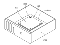
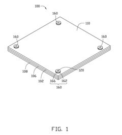
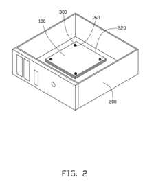
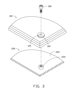
Printed circuit board
PatentInactiveUS20120247825A1
Innovation
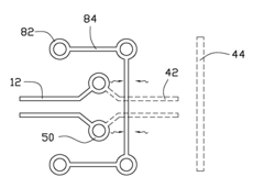
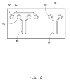
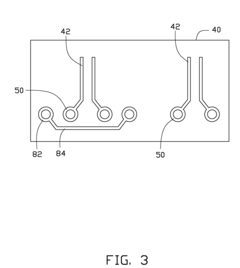
- The solution involves arranging ground vias adjacent to signal vias and using protection lines to electrically connect them, creating a closed loop that isolates noise and interference, preventing it from propagating to other signal lines without increasing the PCB size.
Printed circuit board
PatentInactiveUS20120043113A1
Innovation
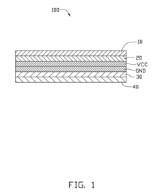
- Integration of ring-shaped electromagnetic wave absorption elements on the PCB, comprising a conductive layer and an absorption layer made of polymer medium and magnetic loss absorption material, which are electrically connected to the ground layer through conductive mount holes and tin rings, to absorb high-frequency noise above 1 GHz, preventing its radiation.
EMC Regulations and Compliance
Electromagnetic Compatibility (EMC) regulations and compliance play a crucial role in the design and implementation of PCB layouts for coil whine reduction. These regulations are established to ensure that electronic devices do not interfere with other equipment or systems and can operate reliably in their intended electromagnetic environment.
The primary regulatory bodies governing EMC standards include the Federal Communications Commission (FCC) in the United States, the European Union's EMC Directive, and the International Special Committee on Radio Interference (CISPR). These organizations set forth specific limits on electromagnetic emissions and susceptibility for various types of electronic equipment.
For PCB layouts aimed at reducing coil whine, compliance with EMC regulations typically involves meeting both conducted and radiated emission limits. Conducted emissions refer to unwanted electromagnetic energy that propagates along power lines or signal cables, while radiated emissions are electromagnetic waves that propagate through space.
To achieve compliance, PCB designers must implement various techniques and strategies. These may include proper component placement, signal routing optimization, and the use of appropriate shielding and filtering mechanisms. Specifically for coil whine reduction, designers need to focus on minimizing the coupling between high-frequency switching circuits and potential resonant structures on the PCB.
EMC testing is an essential part of the compliance process. This involves subjecting the PCB and the overall product to a series of standardized tests in specialized laboratories. These tests evaluate both emissions and immunity across a wide range of frequencies and under various operating conditions.
Failure to meet EMC regulations can result in significant consequences, including product recalls, market access restrictions, and potential legal liabilities. Therefore, it is crucial for PCB designers to consider EMC compliance from the earliest stages of the design process, rather than treating it as an afterthought.
As technology advances and electronic devices become more complex and ubiquitous, EMC regulations continue to evolve. This necessitates ongoing education and adaptation in PCB design practices to ensure continued compliance and optimal performance in reducing coil whine and other electromagnetic issues.
Thermal Management in Reinforced PCB Layouts
Thermal management is a critical aspect of reinforced PCB layouts designed to reduce coil whine. As PCB layouts are reinforced to mitigate electromagnetic vibrations, the increased material density and structural modifications can significantly impact heat dissipation within the circuit board. Effective thermal management strategies are essential to maintain optimal performance and reliability of the reinforced PCB.
One key consideration in thermal management for reinforced PCBs is the use of thermally conductive materials. These materials, such as aluminum nitride or boron nitride, can be incorporated into the PCB substrate or applied as thermal interface materials to enhance heat transfer from components to the board and ultimately to the ambient environment. The strategic placement of these materials in areas prone to heat buildup can significantly improve overall thermal performance.
Another important approach is the implementation of advanced cooling techniques. Heat sinks, for instance, can be integrated directly into the reinforced PCB design to provide localized cooling for high-power components. Additionally, the use of thermal vias – small plated holes that conduct heat between PCB layers – can be optimized in reinforced layouts to create efficient thermal pathways from heat-generating components to cooler areas of the board.
The layout design itself plays a crucial role in thermal management. Careful component placement and trace routing can help distribute heat more evenly across the reinforced PCB. This may involve creating thermal zones, where heat-generating components are grouped together and isolated from sensitive areas. Furthermore, the use of wider traces for power and ground planes can improve heat spreading and reduce thermal resistance.
Active cooling solutions, such as forced-air cooling or liquid cooling systems, may also be necessary for high-power applications. These systems can be designed to work in conjunction with the reinforced PCB layout, ensuring that cooling is directed to the areas most in need of heat dissipation. The integration of temperature sensors and thermal management ICs can provide real-time monitoring and adaptive cooling control, further enhancing the thermal performance of the reinforced PCB.
Simulation and modeling tools play a vital role in optimizing thermal management strategies for reinforced PCB layouts. Computational fluid dynamics (CFD) and finite element analysis (FEA) can be used to predict heat distribution and identify potential hotspots before physical prototyping. These tools allow engineers to iterate on their designs and evaluate the effectiveness of various thermal management techniques in the context of the reinforced PCB structure.
Unlock deeper insights with Patsnap Eureka Quick Research — get a full tech report to explore trends and direct your research. Try now!
Generate Your Research Report Instantly with AI Agent
Supercharge your innovation with Patsnap Eureka AI Agent Platform!