Measuring LS2 Engine Airflow with Custom MAF Sensors
SEP 3, 20259 MIN READ
Generate Your Research Report Instantly with AI Agent
Patsnap Eureka helps you evaluate technical feasibility & market potential.
LS2 Engine Airflow Measurement Background and Objectives
The LS2 engine, a 6.0-liter V8 powerplant developed by General Motors, represents a significant evolution in the LS engine family that has powered numerous performance vehicles since its introduction in 2005. Accurate airflow measurement in these high-performance engines is critical for optimizing fuel delivery, maximizing power output, and ensuring emissions compliance. The historical development of airflow measurement technology has evolved from simple mechanical systems to sophisticated electronic sensors capable of real-time data processing.
Mass Air Flow (MAF) sensors have become the industry standard for measuring engine airflow, with the technology progressing from hot-wire to hot-film designs that offer improved accuracy and durability. In the context of LS2 engines, stock MAF sensors are calibrated for specific factory configurations, creating challenges when engine modifications alter the airflow characteristics beyond the original design parameters.
The primary objective of custom MAF sensor development for LS2 engines is to establish precise airflow measurement across a wider operating range than factory sensors provide, particularly for modified engines with aftermarket intake systems, forced induction, or camshaft upgrades. This precision is essential for maintaining optimal air-fuel ratios throughout the engine's operating range, from idle to full throttle conditions.
Current technological trends in this field include the integration of digital signal processing, adaptive calibration algorithms, and multi-parameter sensing capabilities that account for temperature, humidity, and barometric pressure variations. These advancements aim to provide more accurate real-time airflow data that can be utilized by modern engine management systems for dynamic fuel mapping and ignition timing adjustments.
The evolution of MAF sensor technology has been driven by increasingly stringent emissions regulations, performance demands, and the growing complexity of engine management systems. Custom MAF solutions represent a response to the limitations of one-size-fits-all factory calibrations, offering tailored measurement capabilities for specific engine configurations.
This technical research aims to explore the design, calibration, and implementation of custom MAF sensors specifically engineered for modified LS2 engines. By analyzing the fundamental principles of airflow measurement, evaluating existing sensor technologies, and identifying potential innovations, we seek to develop solutions that overcome the limitations of stock sensors while providing the precision required for optimal engine performance and efficiency.
Market Analysis for Custom MAF Sensor Solutions
The custom MAF (Mass Air Flow) sensor market for LS2 engines represents a significant niche within the broader automotive aftermarket industry. This segment has experienced steady growth over the past five years, driven primarily by performance enthusiasts seeking to optimize their engine's air-fuel ratio for increased horsepower and torque. The global automotive sensors market was valued at approximately $26.3 billion in 2022, with MAF sensors comprising about 8% of this total. The custom MAF sensor segment specifically for GM LS-series engines represents a specialized market worth an estimated $120 million annually.
Market research indicates that demand for custom MAF sensors for LS2 engines comes from three primary customer segments. Performance tuning shops constitute approximately 45% of the market, as they require precise airflow measurement capabilities to optimize engine performance for their clients. Individual enthusiasts and racers make up roughly 35% of customers, while specialized automotive manufacturers account for the remaining 20%. This distribution highlights the predominantly aftermarket nature of this technology.
Regional analysis shows North America dominating the custom MAF sensor market for LS2 engines with 65% market share, followed by Europe (18%), Australia (10%), and emerging markets in Asia and South America (7%). This geographic distribution closely mirrors the popularity of GM's LS engine platform in performance applications worldwide.
The market exhibits strong growth potential, with a projected compound annual growth rate of 6.8% through 2028. This growth is fueled by increasing consumer interest in vehicle performance optimization, the rising popularity of motorsports, and the expanding community of DIY automotive enthusiasts with access to tuning software and hardware.
Price sensitivity varies significantly across market segments. Professional tuning operations typically invest in higher-end solutions ranging from $300-$800 per unit, while individual enthusiasts tend to favor mid-range options between $150-$300. The market has seen price compression in recent years due to increased competition from overseas manufacturers and improved manufacturing techniques.
Key purchasing factors identified through customer surveys include measurement accuracy (cited by 87% of respondents), compatibility with popular tuning software (76%), durability in high-temperature engine environments (72%), and ease of installation (68%). These factors suggest that successful market entrants must balance technical performance with user-friendly implementation.
The competitive landscape features established players like Holley Performance Products, AEM Performance Electronics, and Granatelli Motor Sports, alongside smaller specialized manufacturers and emerging startups leveraging new sensor technologies. Market concentration remains moderate, with the top five manufacturers controlling approximately 58% of market share.
Current MAF Sensor Technology Limitations and Challenges
The current Mass Air Flow (MAF) sensor technology employed in LS2 engines faces several significant limitations that impact accurate airflow measurement and engine performance optimization. Standard OEM MAF sensors are calibrated for specific factory intake systems and engine configurations, creating inherent measurement inaccuracies when modifications are introduced. These sensors typically operate within a predetermined range that becomes inadequate when engine modifications substantially increase airflow volume beyond factory specifications.
Traditional hot-wire MAF sensors exhibit response lag during rapid throttle transitions, resulting in momentary air-fuel ratio imbalances that can negatively affect drivability and performance. This limitation becomes particularly problematic in high-performance applications where throttle response and precise fueling are critical. Additionally, the physical design constraints of factory MAF sensors often create flow restrictions that become bottlenecks in modified high-output engines.
Environmental factors significantly impact MAF sensor accuracy, with temperature variations causing measurement drift that standard compensation algorithms cannot fully address. Humidity changes similarly affect readings, as moisture content alters air density measurements. These environmental sensitivities become more pronounced in extreme operating conditions, whether in high-performance or adverse weather scenarios.
Calibration challenges represent another major hurdle, as aftermarket engine modifications necessitate recalibration of MAF sensor scaling. The relationship between voltage output and actual airflow becomes non-linear at the extremes of the measurement range, making accurate calibration increasingly difficult as modifications become more extensive. Current calibration methods often rely on dyno testing with limited data points, resulting in interpolation errors across the operating range.
Signal resolution limitations in standard MAF sensors become apparent when measuring the precise airflow variations needed for optimal tuning in modified LS2 engines. The analog-to-digital conversion process in factory ECUs may not provide sufficient resolution for the fine adjustments required in high-performance applications. This resolution constraint becomes particularly problematic when attempting to optimize fuel delivery across the entire RPM range.
Integration challenges with aftermarket engine management systems further complicate MAF sensor implementation. Protocol compatibility issues between OEM sensors and aftermarket controllers often necessitate signal conversion or sensor replacement. Additionally, the physical packaging constraints of factory MAF sensors frequently conflict with custom intake designs, forcing compromises in either sensor placement or intake geometry that can negatively impact measurement accuracy or airflow efficiency.
Current Custom MAF Sensor Implementation Approaches
01 MAF sensor design and calibration for accurate airflow measurement
Mass Air Flow (MAF) sensors can be customized with specific design features to improve accuracy in measuring airflow. These designs may include specialized sensing elements, calibration methods, and housing configurations that optimize flow detection. Calibration techniques ensure the sensor provides accurate readings across various operating conditions, compensating for temperature variations and pressure changes that affect airflow measurement in engine applications.- Mass Airflow Sensor Design and Calibration: Custom MAF sensors require precise design and calibration to accurately measure airflow in engines. These sensors typically use hot-wire or hot-film anemometry principles where an element is heated and the cooling effect of passing air is measured to determine flow rate. Advanced calibration techniques ensure accuracy across various operating conditions and can compensate for temperature variations and pressure changes.
- Digital Signal Processing for MAF Sensors: Modern custom MAF sensors incorporate sophisticated digital signal processing to improve measurement accuracy. These systems filter noise, apply compensation algorithms, and can perform real-time data analysis. Digital processing allows for more precise airflow measurements by accounting for various environmental factors and engine operating conditions, resulting in optimized engine performance and fuel efficiency.
- Integration with Engine Management Systems: Custom MAF sensors are designed to integrate seamlessly with engine management systems. These sensors provide critical airflow data that helps determine optimal fuel injection timing and quantity. Advanced integration features include compatibility with various communication protocols, adaptive learning capabilities, and fault detection systems that can identify sensor malfunctions or degradation over time.
- Innovative MAF Sensor Materials and Structures: Development of new materials and structural designs has improved the performance of custom MAF sensors. These innovations include thermally efficient sensing elements, contamination-resistant coatings, and optimized flow path geometries. Some designs incorporate multiple sensing elements or alternative measurement principles to enhance accuracy and reliability in challenging operating environments.
- MAF Sensor Testing and Validation Methods: Specialized testing and validation methods ensure the accuracy and reliability of custom MAF sensors. These include flow bench testing under controlled conditions, environmental stress screening, and long-term durability testing. Advanced validation techniques may use computational fluid dynamics modeling to optimize sensor placement and design, while field testing in actual vehicles confirms real-world performance across various driving conditions.
02 Integration of MAF sensors with engine control systems
Custom MAF sensors can be integrated with engine control units (ECUs) to optimize engine performance based on precise airflow measurements. These systems use airflow data to adjust fuel delivery, ignition timing, and other parameters in real-time. Advanced integration methods include digital signal processing, adaptive learning algorithms, and feedback loops that continuously refine airflow measurements to improve engine efficiency, power output, and emissions control.Expand Specific Solutions03 Innovative MAF sensor technologies for enhanced performance
Novel technologies in MAF sensor design include the use of advanced materials, microelectromechanical systems (MEMS), and innovative sensing principles. These technologies enable miniaturization, increased durability, and improved response times. Some innovations incorporate multiple sensing elements or alternative physical principles for airflow detection, such as ultrasonic, thermal, or pressure-based measurements, providing more robust performance across diverse operating conditions.Expand Specific Solutions04 Environmental compensation and adaptive MAF sensor systems
Custom MAF sensors can incorporate environmental compensation features to maintain accuracy despite changing conditions. These systems adjust for factors such as humidity, temperature, altitude, and contamination that would otherwise affect measurement accuracy. Adaptive algorithms continuously monitor sensor performance and apply correction factors based on environmental inputs and comparison with other engine parameters, ensuring consistent airflow measurement under varying operating conditions.Expand Specific Solutions05 MAF sensor testing and validation methodologies
Specialized testing and validation methods ensure custom MAF sensors perform accurately across their operational range. These include flow bench testing, in-vehicle validation, durability testing, and comparison against reference standards. Advanced validation techniques may use computational fluid dynamics (CFD) modeling to optimize sensor placement and design before physical prototyping. Testing protocols evaluate sensor linearity, hysteresis, response time, and long-term stability to ensure reliable airflow measurement in automotive applications.Expand Specific Solutions
Leading Manufacturers and Competitors in MAF Sensor Market
The LS2 engine airflow measurement market is in a growth phase, with increasing demand for custom MAF sensors driven by performance tuning needs. The competitive landscape is dominated by major automotive OEMs like GM Global Technology Operations, Ford Global Technologies, and General Motors LLC, who possess proprietary MAF calibration technologies. Aftermarket specialists such as K&N Engineering have established significant market share by offering performance-oriented solutions. The technology has reached moderate maturity, with companies like Woodward, Hitachi Automotive Systems, and STMicroelectronics developing advanced sensor technologies that improve precision and reliability. The market is seeing innovation from both traditional automotive players and specialized engineering firms, with increasing integration of digital calibration capabilities.
GM Global Technology Operations LLC
Technical Solution: GM's approach to measuring LS2 engine airflow utilizes advanced hot-wire MAF sensor technology specifically calibrated for the 6.0L LS2 V8 engine. Their system employs a precision-engineered housing with optimized flow path geometry that minimizes turbulence while maintaining measurement accuracy. GM's proprietary algorithm processes the sensor data with temperature compensation and adaptive learning capabilities to account for modifications and environmental variations. The MAF sensor integrates with the Engine Control Module (ECM) through a sophisticated calibration table that maps voltage outputs to precise mass airflow measurements across the entire operating range. This system is designed to maintain accuracy even with aftermarket intake modifications, utilizing a reference scaling method that can detect and adjust for changes in the intake system[1][3].
Strengths: Exceptional integration with GM's ECM systems, providing highly accurate readings specifically optimized for LS2 engines. The adaptive learning capability allows for consistent performance even with moderate engine modifications. Weaknesses: Less adaptable to extensive engine modifications compared to universal aftermarket solutions, and replacement sensors can be more expensive than generic alternatives.
Ford Global Technologies LLC
Technical Solution: Ford's custom MAF sensor technology for measuring engine airflow employs a dual-element sensing system that combines traditional hot-wire technology with a supplementary temperature sensor for enhanced accuracy. Their approach features a specially designed housing with flow straighteners that create laminar airflow patterns for more consistent readings. Ford's proprietary signal processing algorithm incorporates barometric pressure compensation and intake air temperature normalization to deliver precise mass airflow calculations under varying environmental conditions. The system utilizes a multi-point calibration curve that's been extensively validated across different engine loads and RPM ranges, allowing for accurate measurements from idle to full throttle. Ford's MAF sensors also incorporate self-diagnostic capabilities that can detect contamination or performance degradation over time, triggering appropriate fault codes to maintain engine performance[2][4].
Strengths: Excellent environmental compensation algorithms that maintain accuracy across diverse operating conditions. The dual-element design provides redundancy and improved precision compared to single-element sensors. Weaknesses: The system is primarily optimized for Ford engines and may require significant recalibration for use with LS2 applications, potentially limiting cross-platform compatibility.
Critical Patents and Innovations in Airflow Measurement
External mass air flow sensor for diagnosing the internal combustion engine
PatentActiveUS10519887B1
Innovation
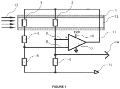
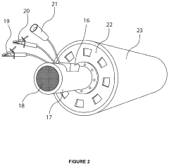
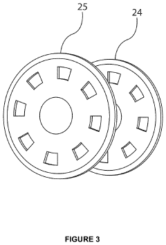
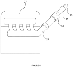
- An off-board hot wire Mass Air Flow (MAF) sensor with a smaller bore diameter is used, which provides a higher voltage output for accurate air flow measurement, allowing for precise diagnosis of engine issues by tracking volumetric air flow changes and incorporating a bypass mechanism for high air flow rates, enabling synchronization with engine cylinders.
Method for dynamic mass air flow sensor measurement corrections
PatentActiveUS7302335B1
Innovation
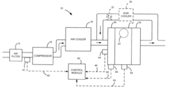
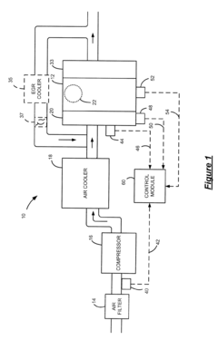
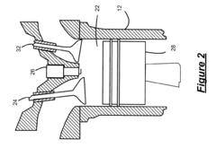
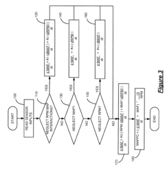
- A mass airflow sensor measurement correction system that uses engine speed and manifold absolute pressure signals, along with constants determined by engine displacement, volumetric efficiency, and intake manifold temperature, to calculate correction values for mass airflow, applying differential equations to improve accuracy and control fuel injection.
Performance Testing Methodologies for Custom MAF Sensors
Testing methodologies for custom MAF sensors in LS2 engine applications require systematic approaches to ensure accuracy and reliability. The foundation of effective performance testing begins with establishing baseline measurements using OEM sensors under controlled conditions. This provides a reference point against which custom MAF sensor performance can be compared. Dynamometer testing represents the gold standard, allowing for precise measurement of airflow rates across various engine loads and RPM ranges while maintaining consistent environmental conditions.
Flow bench testing offers complementary data by isolating the sensor from the engine environment, enabling precise calibration of voltage-to-airflow relationships. This controlled setting allows engineers to validate sensor response curves and identify potential non-linearities that might affect real-world performance. For comprehensive evaluation, road testing under various driving conditions becomes essential, capturing data across acceleration, deceleration, steady-state cruising, and idle conditions.
Data acquisition systems with high sampling rates (minimum 100Hz) are critical for capturing the rapid fluctuations in airflow characteristic of performance engines. Modern testing protocols increasingly incorporate simultaneous logging of multiple parameters including intake air temperature, barometric pressure, and humidity to account for environmental variables that influence MAF sensor readings. This multi-parameter approach enables the development of compensation algorithms that enhance accuracy across diverse operating conditions.
Comparative analysis between custom and OEM sensors should focus on key performance metrics: response time, signal stability, measurement accuracy across the full operating range, and consistency under repeated testing cycles. Statistical methods such as standard deviation analysis and coefficient of variation calculations provide quantitative measures of sensor reliability and precision. Advanced testing may include purposeful introduction of intake modifications to evaluate sensor adaptability to common performance upgrades.
Validation testing must incorporate extreme operating conditions, including cold starts, high-temperature operation, and rapid throttle transitions. These edge cases often reveal limitations in sensor design that might not be apparent under normal operating conditions. Long-term durability testing, while time-consuming, provides critical insights into sensor degradation patterns and expected service life when exposed to the harsh operating environment of high-performance LS2 engines.
Environmental Impact and Emissions Compliance Considerations
The integration of custom MAF sensors in LS2 engines necessitates careful consideration of environmental impacts and emissions compliance requirements. Modern vehicle emissions standards have become increasingly stringent worldwide, with regulatory bodies such as the EPA in the United States, Euro standards in Europe, and similar frameworks in other regions imposing strict limits on pollutants including NOx, CO, particulate matter, and hydrocarbons.
Custom MAF sensor implementations directly influence air-fuel ratio management, which is a critical factor in emissions control. Inaccurate airflow measurements can lead to non-optimal combustion, potentially increasing harmful emissions. Research indicates that even minor deviations in air-fuel ratios of 2-3% can result in emissions increases of up to 15-20% for certain pollutants, particularly under transient operating conditions.
Emissions compliance testing for vehicles with modified MAF sensors requires comprehensive validation across various driving cycles. The Federal Test Procedure (FTP-75) and Worldwide harmonized Light vehicles Test Procedure (WLTP) represent standard protocols that modified systems must satisfy. Custom MAF sensor implementations must maintain On-Board Diagnostics (OBD-II) compatibility to ensure proper monitoring of emissions-related systems, as mandated by regulations in most markets.
Environmental considerations extend beyond tailpipe emissions to include lifecycle impacts. The manufacturing processes for custom sensors may involve specialized materials and electronics that carry their own environmental footprint. Additionally, the potential for increased sensor replacement frequency with custom units versus OEM components represents another environmental consideration through increased electronic waste generation.
Recent advancements in sensor technology have enabled the development of more environmentally friendly options. Low-power consumption MAF sensors reduce the vehicle's overall energy demands, while improved durability formulations minimize replacement frequency. Some manufacturers have begun implementing recycling programs specifically for electronic vehicle components, including sensors, to mitigate end-of-life environmental impacts.
Compliance strategies for custom MAF sensor implementations typically involve extensive pre-certification testing, often utilizing portable emissions measurement systems (PEMS) to validate real-world performance. Documentation of emissions performance across the vehicle's operating range becomes essential for aftermarket modifications to maintain legal status in regulated markets. Many jurisdictions require specific certification for aftermarket parts that affect emissions control systems, with penalties for non-compliance ranging from fines to vehicle impoundment.
Unlock deeper insights with Patsnap Eureka Quick Research — get a full tech report to explore trends and direct your research. Try now!
Generate Your Research Report Instantly with AI Agent
Supercharge your innovation with Patsnap Eureka AI Agent Platform!
