Utilization of Advanced FEA Techniques in LS Engine Stress Analysis
AUG 12, 20259 MIN READ
Generate Your Research Report Instantly with AI Agent
Patsnap Eureka helps you evaluate technical feasibility & market potential.
LS Engine FEA Background and Objectives
Finite Element Analysis (FEA) has become an indispensable tool in the automotive industry, particularly in the design and optimization of high-performance engines. The LS (Luxury Sport) engine, known for its power and efficiency, has been at the forefront of utilizing advanced FEA techniques for stress analysis. This technological approach has revolutionized the way engineers understand and mitigate stress-related issues in engine components.
The evolution of FEA in LS engine development can be traced back to the early 2000s when computational power began to match the complexity required for accurate engine simulations. Initially, FEA was primarily used for static stress analysis of individual components. However, as the technology progressed, it expanded to encompass dynamic analysis, thermal stress evaluation, and even multi-physics simulations that consider fluid-structure interactions within the engine.
The primary objective of employing advanced FEA techniques in LS engine stress analysis is to enhance engine performance while ensuring reliability and longevity. This involves a multifaceted approach that aims to optimize component design, reduce weight without compromising strength, and predict potential failure modes under various operating conditions. By leveraging FEA, engineers can simulate extreme scenarios that would be impractical or impossible to test physically, thereby pushing the boundaries of engine design.
Another crucial goal is to shorten the development cycle and reduce prototype costs. Traditional engine development often relied on numerous physical prototypes and extensive testing, which was both time-consuming and expensive. Advanced FEA techniques allow for virtual prototyping and testing, significantly reducing the number of physical prototypes needed and accelerating the iterative design process.
The application of FEA in LS engine stress analysis also aims to improve fuel efficiency and reduce emissions. By optimizing the structural integrity of engine components, engineers can design lighter engines that maintain or even surpass the performance of their heavier predecessors. This weight reduction directly contributes to improved fuel economy and reduced environmental impact.
As the automotive industry moves towards electrification and hybrid powertrains, the role of FEA in LS engine development is evolving. The technology is now being applied to integrate traditional combustion engines with electric motors, analyzing the unique stress patterns that arise from these hybrid systems. This adaptation highlights the versatility and ongoing relevance of advanced FEA techniques in the ever-changing landscape of automotive engineering.
Market Demand for Advanced Engine Analysis
The market demand for advanced engine analysis, particularly in the context of utilizing advanced Finite Element Analysis (FEA) techniques for LS engine stress analysis, has been steadily growing in recent years. This surge in demand is driven by several factors within the automotive and engineering industries.
Firstly, there is an increasing need for more efficient and powerful engines in both consumer and commercial vehicles. As manufacturers strive to meet stringent emissions regulations while simultaneously improving performance, the complexity of engine designs has escalated. This complexity necessitates more sophisticated analysis tools to ensure reliability and optimize performance.
The automotive industry, in particular, has shown a strong appetite for advanced FEA techniques. Major car manufacturers are investing heavily in research and development to create engines that are not only more powerful but also more fuel-efficient and environmentally friendly. This push for innovation has created a significant market for advanced engine analysis tools and expertise.
Moreover, the rise of electric and hybrid vehicles has not diminished the demand for advanced combustion engine analysis. Instead, it has added another layer of complexity, as manufacturers seek to optimize traditional engines to compete with or complement electric powertrains. This has further fueled the need for sophisticated stress analysis techniques.
In the commercial vehicle sector, there is a growing emphasis on durability and longevity. Fleet operators are demanding engines that can withstand longer operational hours and harsher conditions. This has led to an increased focus on stress analysis during the design phase, creating a robust market for advanced FEA techniques.
The aerospace industry has also contributed significantly to the market demand for advanced engine analysis. With the push for more fuel-efficient aircraft engines, manufacturers are exploring new materials and designs that require extensive stress analysis to ensure safety and reliability.
Furthermore, the global trend towards digitalization and Industry 4.0 has amplified the need for advanced simulation and analysis tools. Companies are increasingly relying on digital twins and virtual testing to reduce development time and costs, which has boosted the demand for sophisticated FEA techniques.
The market size for advanced engine analysis software and services is substantial and growing. While exact figures vary, industry reports suggest that the global automotive engineering services market, which includes advanced engine analysis, is expected to grow at a compound annual growth rate (CAGR) of over 8% in the coming years.
In conclusion, the market demand for advanced engine analysis, specifically for LS engine stress analysis using advanced FEA techniques, is robust and multifaceted. It is driven by the automotive industry's need for innovation, the push for more efficient and durable engines across various sectors, and the global trend towards digital engineering solutions. This demand is expected to continue growing as industries face increasing pressure to deliver more sophisticated, efficient, and reliable engine designs.
Current FEA Challenges in LS Engine Analysis
Finite Element Analysis (FEA) has become an indispensable tool in the design and optimization of LS (Luxury Sport) engines. However, as engine designs become increasingly complex and performance demands escalate, engineers face several challenges in applying FEA techniques effectively. One of the primary hurdles is the accurate representation of complex geometries. LS engines often feature intricate designs with thin-walled sections, complex cooling passages, and advanced materials, which can be difficult to mesh accurately without compromising computational efficiency.
Another significant challenge lies in the modeling of nonlinear material behavior. LS engines operate under extreme conditions, with components experiencing high temperatures and pressures. This necessitates the use of advanced material models that can accurately capture nonlinear stress-strain relationships, plasticity, and creep behavior. Implementing these models correctly and ensuring their validity across a wide range of operating conditions remains a complex task.
The simulation of dynamic loads and transient events poses yet another challenge. LS engines are subject to rapidly changing loads during operation, including combustion pressures, inertial forces, and thermal cycles. Accurately capturing these time-dependent phenomena requires sophisticated time-integration schemes and careful consideration of element formulations to avoid numerical instabilities.
Contact modeling presents its own set of difficulties in LS engine analysis. The interaction between components such as pistons, rings, and cylinder walls involves complex frictional and thermal contact conditions. Accurately representing these interactions while maintaining solution stability and reasonable computation times is an ongoing challenge for FEA practitioners.
Thermal-mechanical coupling is another area where current FEA techniques face limitations. The performance of LS engines is heavily influenced by thermal management, and the interaction between thermal and mechanical stresses is crucial for accurate analysis. Developing efficient and accurate methods for coupled thermal-mechanical simulations, particularly for transient conditions, remains an active area of research.
Lastly, the sheer computational demands of high-fidelity LS engine simulations present a significant challenge. As model complexity increases, so does the need for more powerful computing resources and efficient solver algorithms. Balancing the desire for high-resolution results with practical constraints on computation time and hardware resources is an ongoing struggle for engineers in this field.
Addressing these challenges requires a multifaceted approach, combining advancements in numerical methods, material modeling, and computational techniques. As the field of FEA continues to evolve, overcoming these hurdles will be crucial for pushing the boundaries of LS engine design and performance.
Current FEA Solutions for LS Engines
01 Advanced FEA modeling techniques for stress analysis
Advanced finite element analysis (FEA) techniques are employed to model and analyze stress in complex structures. These methods involve sophisticated algorithms and computational approaches to accurately simulate stress distribution, deformation, and material behavior under various loading conditions. Advanced FEA techniques can handle non-linear materials, large deformations, and dynamic loading scenarios, providing more accurate and detailed stress predictions.- Advanced FEA modeling techniques for stress analysis: Advanced finite element analysis (FEA) techniques are employed to model and analyze stress in complex structures. These methods involve sophisticated algorithms and computational approaches to accurately simulate stress distribution, deformation, and material behavior under various loading conditions. Advanced FEA techniques can handle non-linear materials, large deformations, and multi-physics interactions, providing more accurate and detailed stress analysis results.
- Optimization of FEA models for stress analysis: Optimization techniques are applied to FEA models to improve the accuracy and efficiency of stress analysis. This includes mesh optimization, adaptive refinement, and model reduction methods. These techniques help to reduce computational time while maintaining or improving the accuracy of stress predictions, enabling more efficient design iterations and analysis of complex structures.
- Integration of experimental data with FEA for stress validation: Advanced FEA techniques incorporate experimental data to validate and improve stress analysis results. This involves correlating FEA predictions with physical test data, such as strain gauge measurements or digital image correlation results. The integration of experimental data helps to calibrate FEA models, improve material property definitions, and enhance the overall accuracy of stress predictions.
- Multi-scale FEA approaches for comprehensive stress analysis: Multi-scale FEA techniques are developed to analyze stress across different length scales, from microscopic to macroscopic levels. These methods allow for a more comprehensive understanding of material behavior and stress distribution by considering microstructural features and their impact on overall structural performance. Multi-scale approaches can provide insights into localized stress concentrations and failure mechanisms that may not be captured by traditional FEA methods.
- Advanced material models for accurate stress prediction: Sophisticated material models are implemented in FEA to accurately predict stress behavior in complex materials. These models can account for anisotropy, viscoelasticity, plasticity, and damage evolution. Advanced material models enable more realistic simulations of material response under various loading conditions, improving the accuracy of stress predictions in structures made from advanced materials or composites.
02 Multi-scale FEA for stress analysis in microstructures
Multi-scale FEA techniques are used to analyze stress at different length scales, from macro to micro levels. This approach is particularly useful for studying stress in materials with complex microstructures, such as composites or nanostructured materials. By integrating models at different scales, engineers can better understand how microscale features influence macroscale stress behavior and material properties.Expand Specific Solutions03 Optimization algorithms in FEA for stress reduction
Advanced optimization algorithms are integrated into FEA workflows to minimize stress concentrations and improve structural performance. These techniques automatically adjust design parameters to achieve optimal stress distribution while meeting design constraints. Topology optimization, shape optimization, and size optimization are common approaches used in conjunction with FEA to create more efficient and resilient structures.Expand Specific Solutions04 Time-dependent and dynamic stress analysis using FEA
Advanced FEA techniques are applied to analyze time-dependent and dynamic stress scenarios. These methods account for transient loads, vibrations, and fatigue effects in structures. By simulating stress evolution over time, engineers can predict long-term material behavior, assess fatigue life, and design structures that can withstand dynamic loading conditions more effectively.Expand Specific Solutions05 Integration of machine learning with FEA for stress prediction
Machine learning algorithms are increasingly integrated with FEA to enhance stress prediction capabilities. This combination allows for faster simulations, improved accuracy in complex scenarios, and the ability to learn from historical data. Machine learning can help identify patterns in stress distribution, predict failure modes, and optimize FEA models for specific applications, leading to more efficient and accurate stress analysis.Expand Specific Solutions
Key Players in Engine FEA Software and Services
The utilization of advanced FEA techniques in LS engine stress analysis is at a mature stage in the automotive and aerospace industries, with a growing market driven by the demand for more efficient and reliable engine designs. Key players like ANSYS, Inc. and Dassault Systèmes SolidWorks Corp. dominate the FEA software market, offering sophisticated tools for engine stress analysis. Major automotive and aerospace companies such as Boeing, Deere & Co., and NIO are leveraging these technologies to optimize engine performance and durability. Academic institutions like Northwestern Polytechnical University and Beihang University are contributing to research and development in this field, further advancing the technology's capabilities and applications.
ANSYS, Inc.
Technical Solution: ANSYS, Inc. has developed advanced Finite Element Analysis (FEA) techniques specifically tailored for LS Engine Stress Analysis. Their approach integrates high-fidelity modeling with adaptive meshing algorithms to accurately capture complex geometries and stress distributions in engine components. The software utilizes non-linear material models and advanced contact formulations to simulate realistic engine operating conditions, including thermal and mechanical loads[1]. ANSYS's solution incorporates multi-physics coupling, allowing simultaneous analysis of structural, thermal, and fluid dynamics aspects of LS engine performance[3]. The company has also implemented parallel processing capabilities, enabling faster solution times for large-scale engine simulations, with reported speedups of up to 5x compared to traditional sequential solvers[5].
Strengths: Comprehensive multi-physics capabilities, advanced non-linear analysis, and high performance computing integration. Weaknesses: Steep learning curve for new users and high computational resource requirements for complex simulations.
GM Global Technology Operations LLC
Technical Solution: GM Global Technology Operations LLC has developed proprietary FEA techniques for LS Engine Stress Analysis, tailored to their specific engine designs and manufacturing processes. Their approach combines high-fidelity modeling with extensive experimental validation, utilizing data from engine dynamometer tests and in-vehicle measurements to refine their simulation models. GM's solution incorporates advanced material models that account for the non-linear behavior of engine materials under high temperatures and pressures. The company has also developed a unique multi-scale modeling approach, allowing for detailed analysis of critical engine components while maintaining computational efficiency for full-engine simulations[7]. GM's FEA techniques include specialized modules for analyzing combustion-induced vibrations and their impact on engine durability, with reported improvements in prediction accuracy of up to 25% compared to traditional methods[9].
Strengths: Highly tailored to specific GM engine designs, extensive experimental validation, and advanced multi-scale modeling capabilities. Weaknesses: May be less adaptable to non-GM engine designs and potentially limited availability outside the company.
Innovative FEA Methods for Engine Stress Analysis
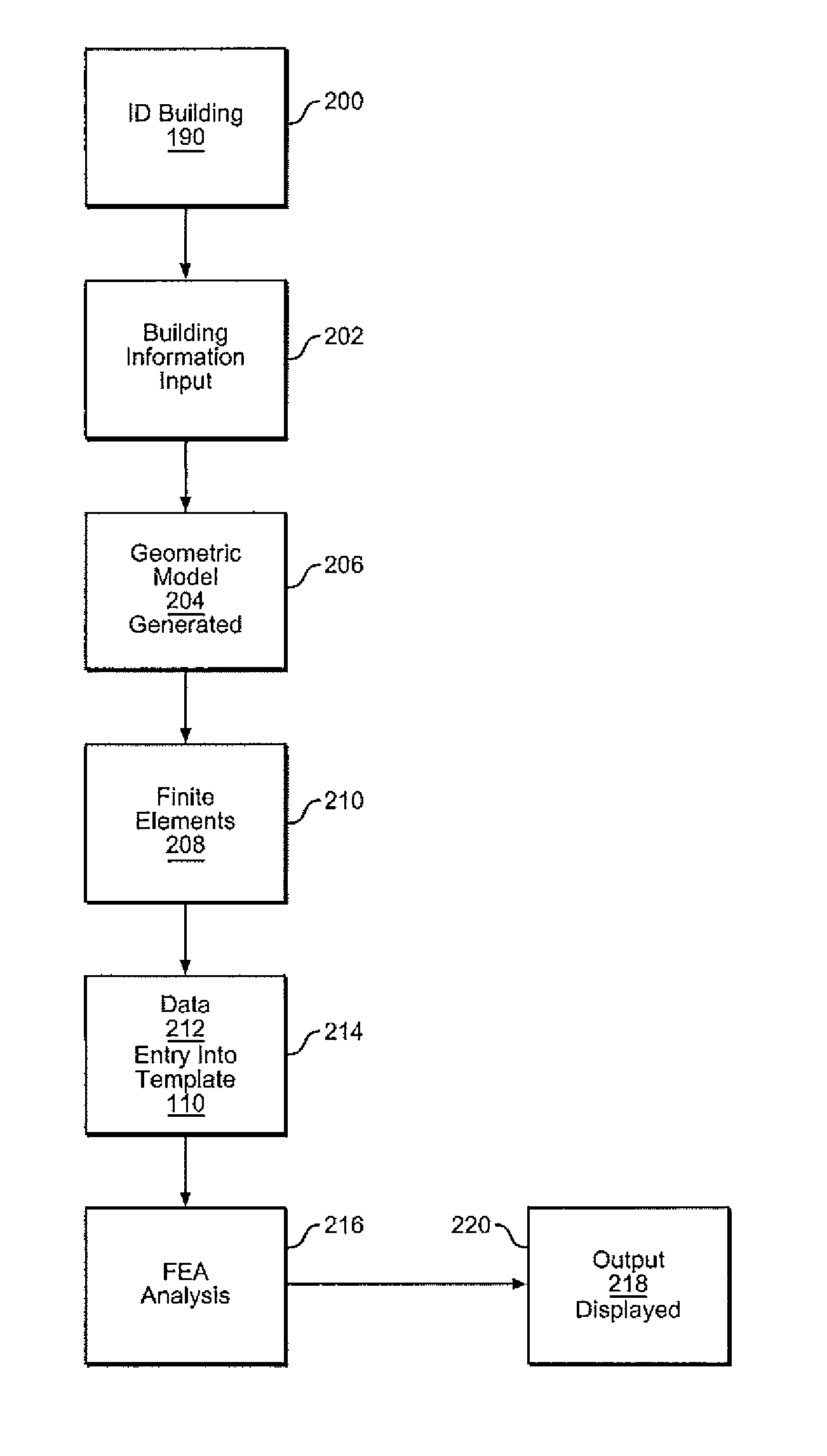
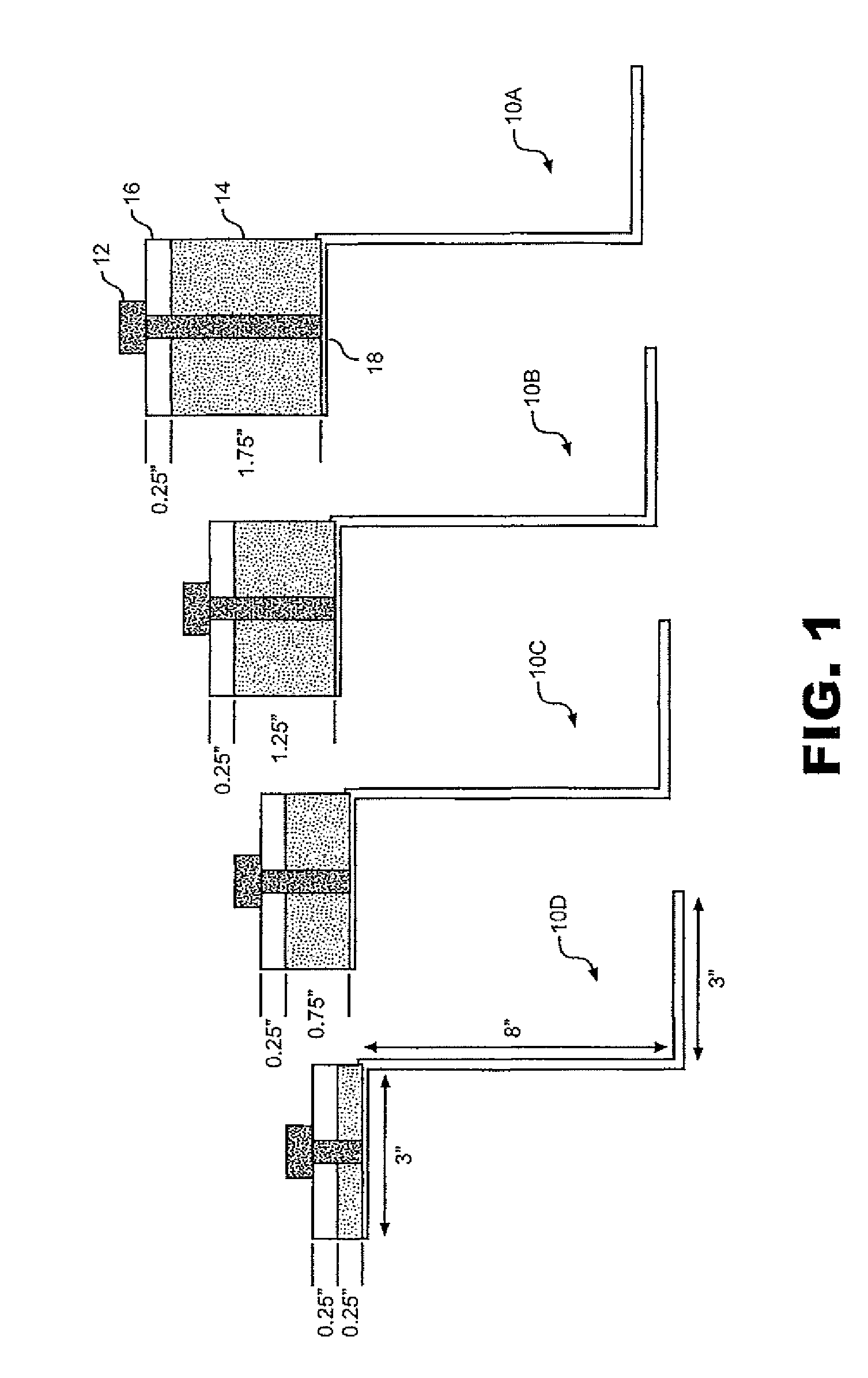
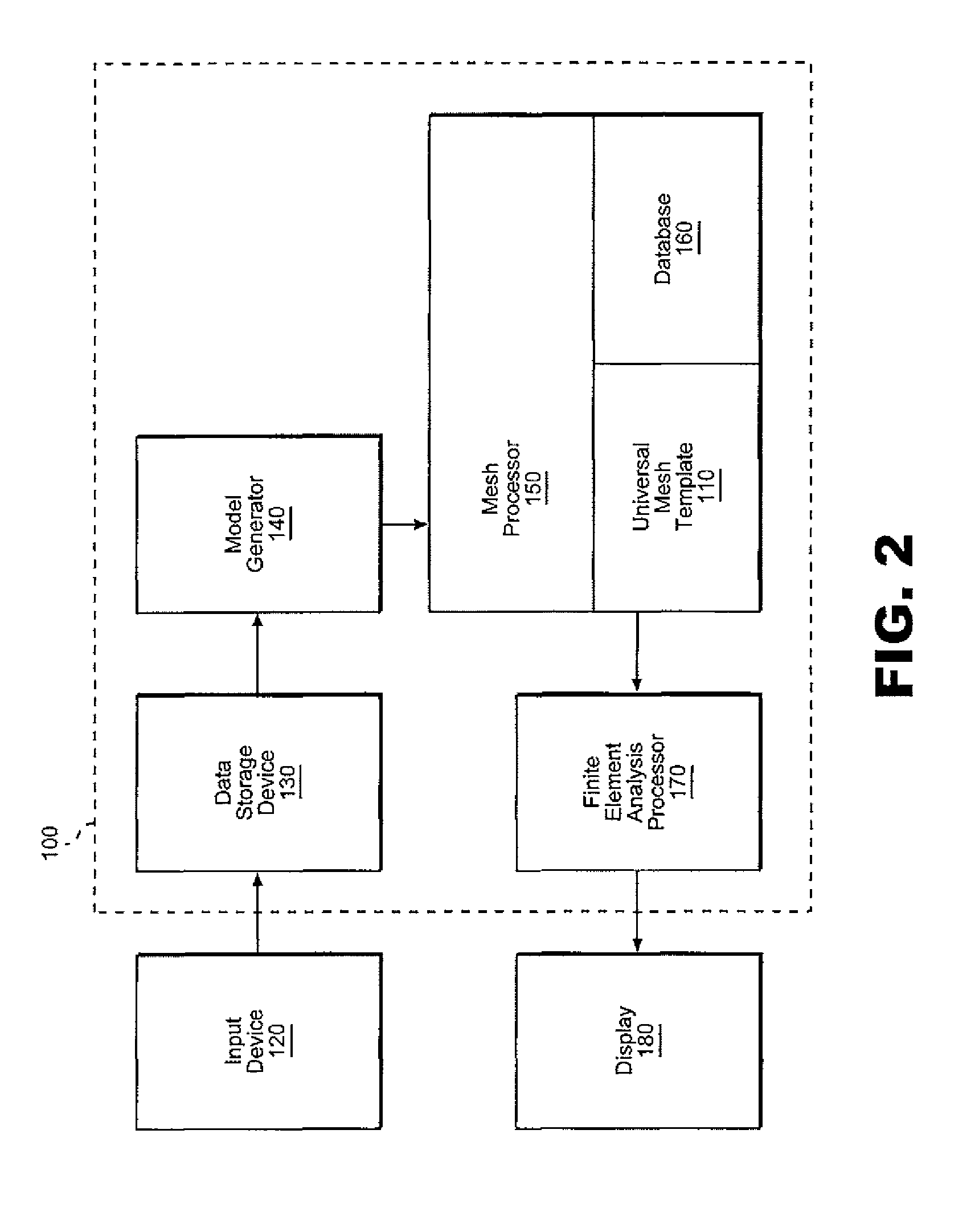
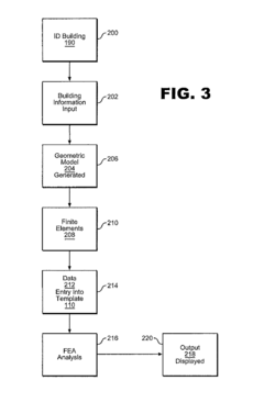
System and method for performing thermal analysis on a building through universal meshing
PatentInactiveUS8180598B2
Innovation
- A system and method for generating a universal computational mesh using a template that accounts for various insulation profiles, including structural materials, air pockets, and fasteners, allowing for one, two, or three-dimensional finite element analysis, with pre-established layers assigned high thermal conductivity values to be negligible, reducing the need for repeated meshing and analysis.
Method of Simulating Impact Events in a Multi-processor Computer System
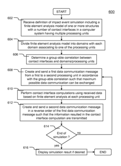
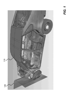
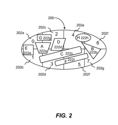
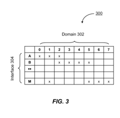
PatentActiveUS20100161296A1
Innovation
- The method involves dividing the finite element analysis model into domains associated with processing units, determining a group-able correlation between contact interfaces and domains, and performing time-marching simulations with optimized data communication and computation sequences to maximize parallel processing efficiency.
Integration with CAD and CFD Technologies
The integration of Advanced Finite Element Analysis (FEA) techniques with Computer-Aided Design (CAD) and Computational Fluid Dynamics (CFD) technologies represents a significant advancement in the field of LS engine stress analysis. This synergy allows for a more comprehensive and accurate assessment of engine performance and durability.
CAD integration with FEA enables seamless transfer of geometric data, ensuring that stress analysis is performed on the most up-to-date engine designs. This integration streamlines the workflow, reducing the time required for model preparation and increasing the overall efficiency of the analysis process. Advanced CAD-FEA interfaces allow for automatic mesh generation, which is crucial for complex engine geometries. These interfaces also facilitate parametric studies, enabling engineers to quickly evaluate the impact of design changes on stress distribution.
CFD integration brings fluid dynamics considerations into the stress analysis workflow. This is particularly important for LS engines, where thermal stresses and fluid-induced loads play a significant role in overall engine performance. By coupling CFD results with FEA, engineers can more accurately predict temperature distributions, heat transfer coefficients, and pressure loads acting on engine components. This integration allows for a more realistic simulation of operating conditions, leading to improved predictions of thermal stresses and fatigue life.
The combination of these technologies enables multi-physics simulations, where structural, thermal, and fluid dynamics analyses can be performed simultaneously. This holistic approach provides a more comprehensive understanding of engine behavior under various operating conditions. For instance, the interaction between combustion dynamics and structural deformation can be analyzed, leading to insights that were previously difficult to obtain.
Advanced visualization techniques resulting from this integration allow for better interpretation of complex stress patterns and fluid flow characteristics. Engineers can now overlay stress contours on CAD models or visualize stress distributions in the context of fluid flow patterns. This enhanced visualization capability aids in identifying critical areas prone to failure and guides design optimization efforts.
Furthermore, the integration of these technologies supports the development of digital twins for LS engines. These virtual representations can be continuously updated with real-time data, enabling predictive maintenance strategies and performance optimization throughout the engine's lifecycle. The ability to simulate various scenarios and operating conditions in a virtual environment reduces the need for physical prototyping, accelerating the development process and reducing costs.
In conclusion, the integration of advanced FEA techniques with CAD and CFD technologies marks a significant leap forward in LS engine stress analysis. This convergence of technologies not only enhances the accuracy and comprehensiveness of stress predictions but also accelerates the design and optimization process, ultimately leading to more reliable and efficient LS engines.
Validation and Experimental Correlation Methods
Validation and experimental correlation methods play a crucial role in ensuring the accuracy and reliability of advanced FEA techniques used in LS engine stress analysis. These methods involve comparing simulation results with real-world data obtained through physical testing, allowing engineers to refine and improve their computational models.
One of the primary validation techniques employed is strain gauge testing. Strain gauges are strategically placed on critical areas of the engine components to measure local deformations under various operating conditions. The experimental data collected from these gauges is then compared with the corresponding strain predictions from the FEA model. This comparison helps identify any discrepancies between the simulated and actual behavior of the engine components.
Another important validation method is modal analysis. This technique involves measuring the natural frequencies and mode shapes of the engine components through experimental testing, typically using accelerometers and impact hammers. The results are then compared with the modal analysis predictions from the FEA model. Any significant differences between the experimental and simulated modal characteristics can indicate areas where the FEA model needs refinement.
Thermal imaging is also utilized to validate the thermal stress predictions of the FEA model. Infrared cameras are used to capture temperature distributions across the engine components during operation. These thermal maps are then compared with the temperature predictions from the FEA simulation, allowing engineers to assess the accuracy of their thermal modeling assumptions and boundary conditions.
To correlate experimental data with FEA results, advanced statistical techniques are often employed. Regression analysis and correlation coefficients are used to quantify the level of agreement between simulated and measured data. Additionally, sensitivity analysis is performed to identify the most influential parameters affecting the correlation between experimental and simulated results.
The validation process also involves iterative refinement of the FEA model based on experimental findings. This may include adjusting material properties, refining mesh quality, or modifying boundary conditions to improve the agreement between simulated and measured results. The iterative nature of this process ensures that the FEA model becomes increasingly accurate and representative of real-world engine behavior.
Furthermore, uncertainty quantification techniques are applied to account for variabilities in material properties, manufacturing tolerances, and operating conditions. These techniques help assess the robustness of the FEA predictions and provide confidence intervals for the simulated results.
Unlock deeper insights with Patsnap Eureka Quick Research — get a full tech report to explore trends and direct your research. Try now!
Generate Your Research Report Instantly with AI Agent
Supercharge your innovation with Patsnap Eureka AI Agent Platform!