Mixed light controlling unit

A technology of control unit and light emitting unit, which is applied in the direction of material size control, non-electric variable control, control/regulation system, etc., and can solve problems such as poor effect and increased cost

Active Publication Date: 2009-01-07
AU OPTRONICS CORP
View PDF4 Cites 0 Cited by
  • Summary
  • Abstract
  • Description
  • Claims
  • Application Information

AI Technical Summary

Problems solved by technology

[0005] However, in the existing light mixing control unit, since the red light detection unit 10R, the green light detection unit 10G, and the blue light detection unit 10B must be respectively added with a red filter 14R, a green filter 14G, and a blue The optical filter 14B makes the effect of receiving light of the three-color detection unit poor, and in addition, increases the cost

Method used


Image

  • Mixed light controlling unit
  • Mixed light controlling unit

Examples


Embodiment Construction

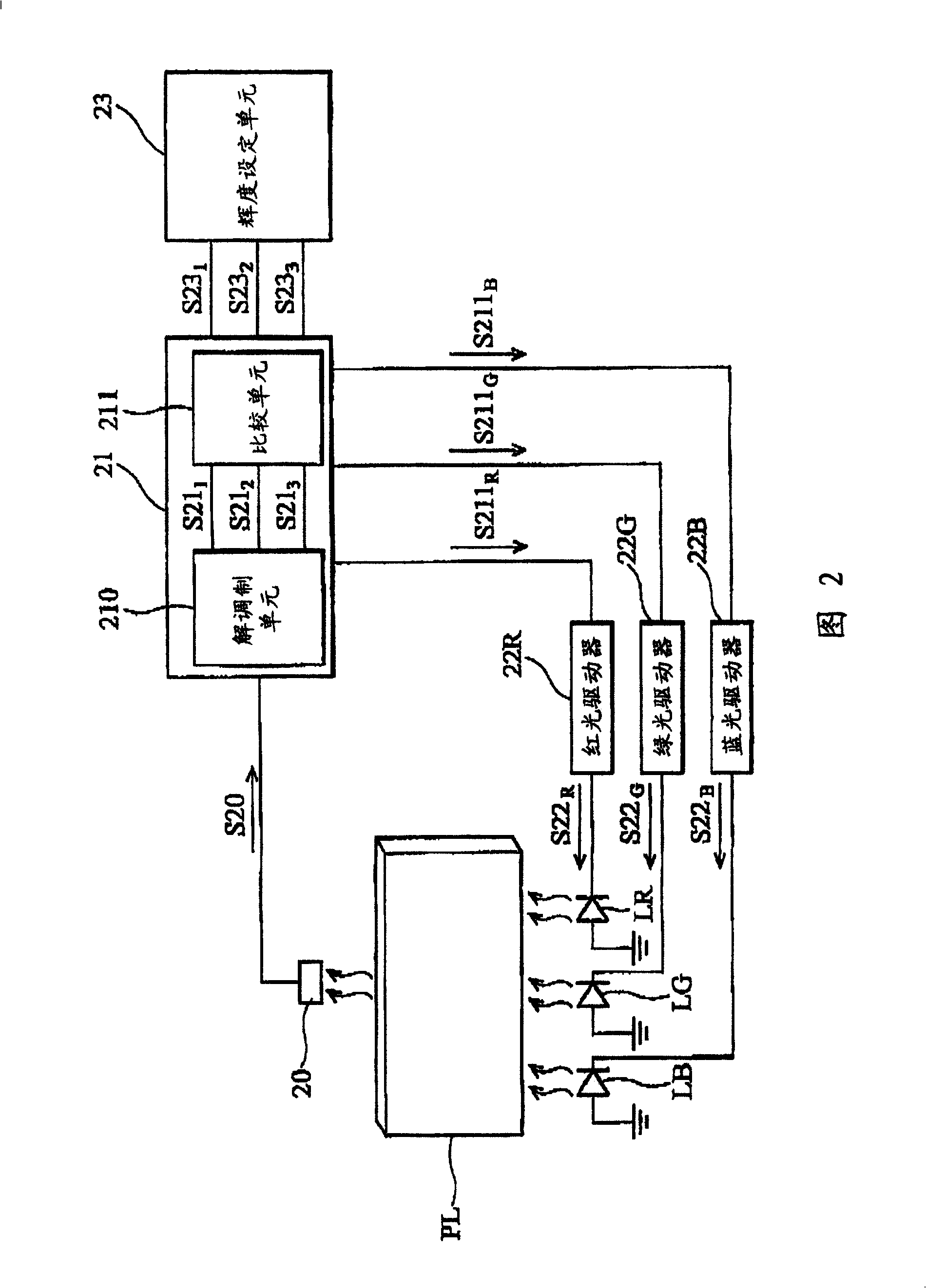
[0013] Fig. 2 is a schematic diagram showing the light mixing control unit of the present invention. The light mixing control unit 2 is suitable for a display. The mixed light control unit 2 includes a light detection unit 20 , a control unit 21 , a red light driver 22R, a green light driver 22R, a blue light driver 22B, and a luminance setting unit 23 . The red LED LR, green LED LG, and blue LED LB of the backlight module in the panel PL are arranged under the panel PL.

[0014] The red light driver 22R drives the signal S22 with the red light carrying the first frequency R to drive the red LED LR, the green driver 22G to carry the green driving signal S22 of the second frequency G to drive the green LED LG at a high rate, and the blue driver 22B to carry the blue driving signal S22 of the third frequency B To drive the blue LED LB, it means that the operating frequencies of the red LED LR, green LED LG, and blue LED LB are the first, second, and third frequencies respecti...


PUM


Abstract

A control unit prepares mixed light by driving two luminous devices on back light module with the first and the second frequencies. The unit is featured as calculating out energy of abovesaid two frequencies according to detection signal, controlling the first driver to adjust energy of the first frequency based on difference between energies of the first frequency and the first preset frequency as well as applying the same thing to the second ones to adjust energy of the second frequency.

Description

technical field [0001] The invention relates to a light mixing control unit, in particular to a light mixing control unit, which is suitable for a display device and used for adjusting the white light color coordinates of a backlight source. Background technique [0002] In a liquid crystal display (liquid crystal display, LCD) device, the backlight module usually utilizes light emitting diodes (Light Emitting Diodes, LED) as the backlight of the LCD device. LED backlight can generally be divided into two types, one is to directly use white LED as backlight, but the cost of white LED is high; the other is to use red, green and blue LED as backlight, which is to use red, green The red light, green light, and blue light emitted by the blue and blue tri-color LEDs are mixed to produce white light. Generally speaking, in order to detect whether the mixed white light meets the preset standard, the backlight module uses the mixed light control unit to adjust the intensity of the ...

Claims


Application Information

Patent Timeline
Patent Type & Authority Patents(China)
IPC IPC(8): G02F1/1335G09G3/36G02F1/01G05D5/00
Inventor 高克嘉陈志光黄志濠
Owner AU OPTRONICS CORP
Why Eureka
Try Eureka