Saunas arrangement

A sauna and air supply technology, applied in the field of sauna devices, can solve problems such as uneven temperature and humidity, water droplets attached to glasses, difficult to control temperature and humidity, etc., and achieve excellent temperature and humidity distribution

Active Publication Date: 2008-01-30
PANASONIC CORP
View PDF1 Cites 21 Cited by
  • Summary
  • Abstract
  • Description
  • Claims
  • Application Information

AI Technical Summary

Problems solved by technology

[0005] In such a conventional spraying device, since only the heated air is discharged from the exhaust port 106, the mist is sprayed independently by the mist ejection part 111, so there is humidified air and mist that are not mixed, resulting in a mist due to temperature and humidity. The problem of uneven temperature and humidity, and what people want is to mix temperature and humidity to obtain uniform temperature and humidity
[0006] In addition, since the mist is inde

Method used


Image

  • Saunas arrangement
  • Saunas arrangement
  • Saunas arrangement

Examples


Example Embodiment

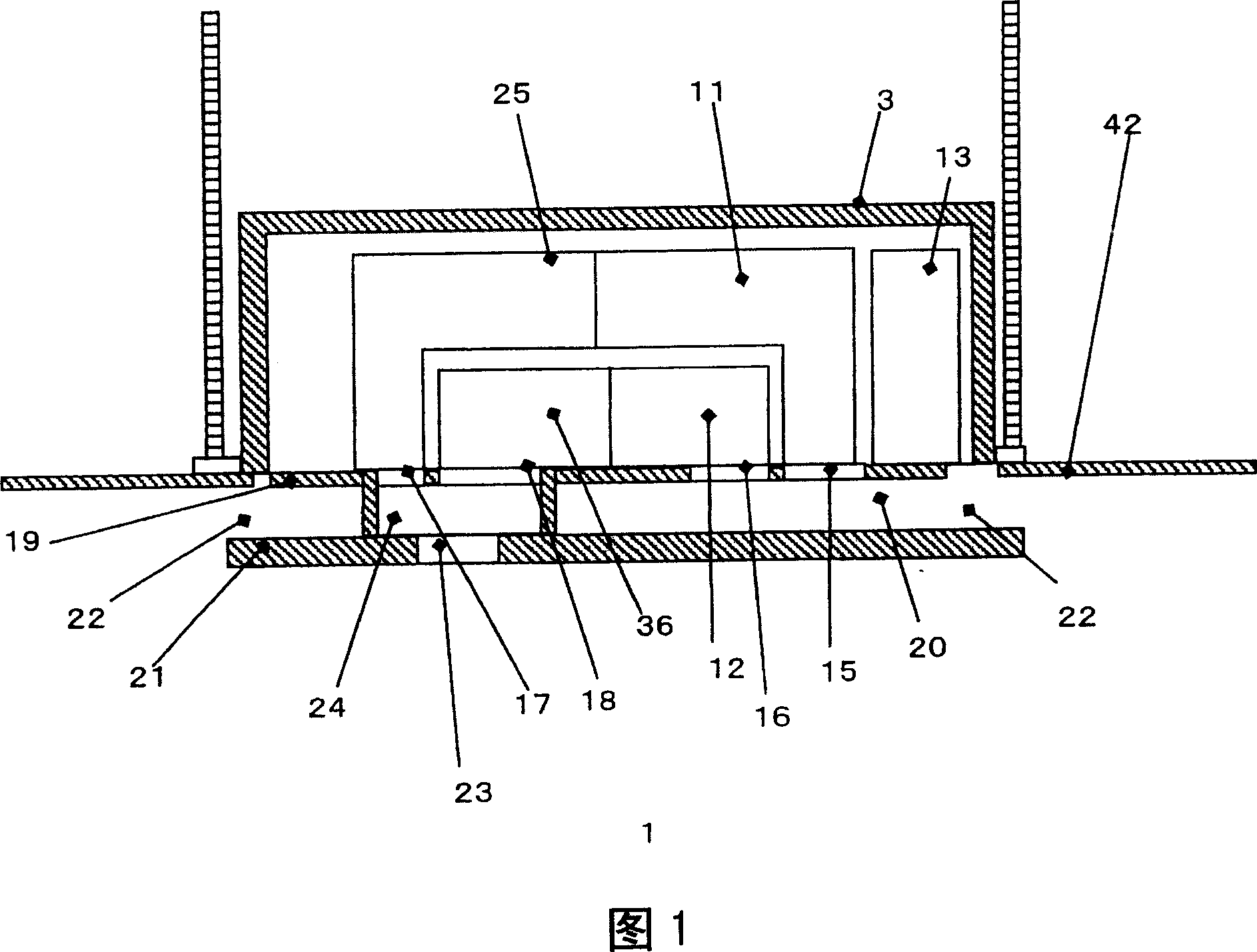
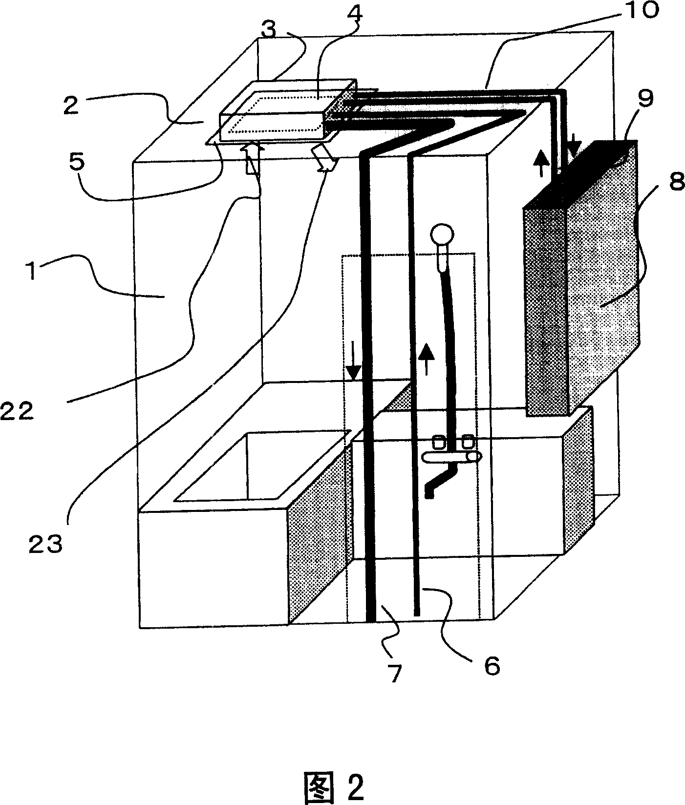
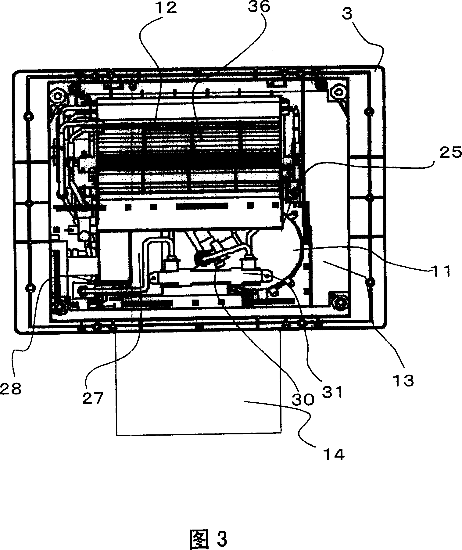
[0035] As shown in Figures 1 to 5, a device body 3 forming a sauna device is provided in a ceiling space 2 of a sauna object room 1 composed of a bathroom or the like, and an opening 4 formed under the device body 3 passes through a ceiling opening 5. It communicates with the sauna object room 1. In addition, a water supply pipe 6 for supplying water or warm water to the apparatus body 3 and a drain pipe 7 for discharging water discharged from the apparatus body 3 are connected to the apparatus body 3, and a water heater 8 as a heat source is connected to a water heater 8 as a heat source. The circulating warm water circuit outlet pipe 9 and the circulating warm water circuit returning pipe 10 of the warm water circulation circuit on the heat source side perform the following actions when heating the inside of the sauna object room 1 and the device body 3, that is, warm water passes through the water supply heater 8 through the circulation The warm water circuit is sent into t...


PUM


Abstract

The present invention provides a sauna device which can obtain the uniform temperature and humidity. The sauna device includes: a heating air supply part (36), which transfers the air which is heated by a heating part (12) to heat the air; a humidifying part (11); a humidifying air supply part (25), which transfers the air which is humidified by the humidifying part (11); a suction inlet (22); and an exhaust outlet (23), wherein, the confluence of the heated air from the heating air supply part (36) and the humidified air from the humidifying air supply part (25) is in front of the exhaust outlet (23), and then the air after the heating and humidifying is exhausted from the exhaust outlet (23), so the present invention can get the sauna device which can obtain the uniform temperature and humidity.

Description

technical field [0001] The present invention relates to a sauna device that forms the inside of a bathroom into a high-temperature and high-humidity sauna space. Background technique [0002] Conventionally, as an example of such a sauna device, a spray device installed on the ceiling of a bathroom to form a sauna room is known (for example, refer to JP-A-2002-336327). [0003] Next, such a spray device will be described with reference to FIG. 6 . [0004] As shown in the figure, this spraying device is constituted as follows, that is, a grille plate 104 that will be provided with a device body 103 covered with a circulation fan 101 and a movable ventilation window 102 is provided, and the device body 103 includes: a circulation ventilation path 107, which It is used to draw the indoor air into the housing 103a through the suction port 105, and discharge the air from the exhaust port 106; the circulation fan 101, which exerts a ventilation effect on the circulation ventilat...

Claims


Application Information

Patent Timeline
IPC IPC(8): A61H33/06
Inventor 藤井聪五十里良雄
Owner PANASONIC CORP
Why Eureka
Try Eureka