Form component forming mould

A formwork component and forming mold technology, applied in the direction of molds, mold separation devices, etc., can solve the problems of easy damage of thin-walled boxes and inconvenient demoulding

Inactive Publication Date: 2008-04-23
湖南邱则有专利战略策划有限公司
View PDF2 Cites 1 Cited by
  • Summary
  • Abstract
  • Description
  • Claims
  • Application Information

AI Technical Summary

Problems solved by technology

Such as the positive mold, as can be seen from their drawings, it includes a side mold surface and a lower mold surface (or a top mold surface), and the side mold surface and the lower mold surface form a male mold, which is the male mo...

Method used


Image

  • Form component forming mould
  • Form component forming mould
  • Form component forming mould

Examples


Embodiment Construction

[0061] The present invention will be further described below in conjunction with the accompanying drawings and embodiments.

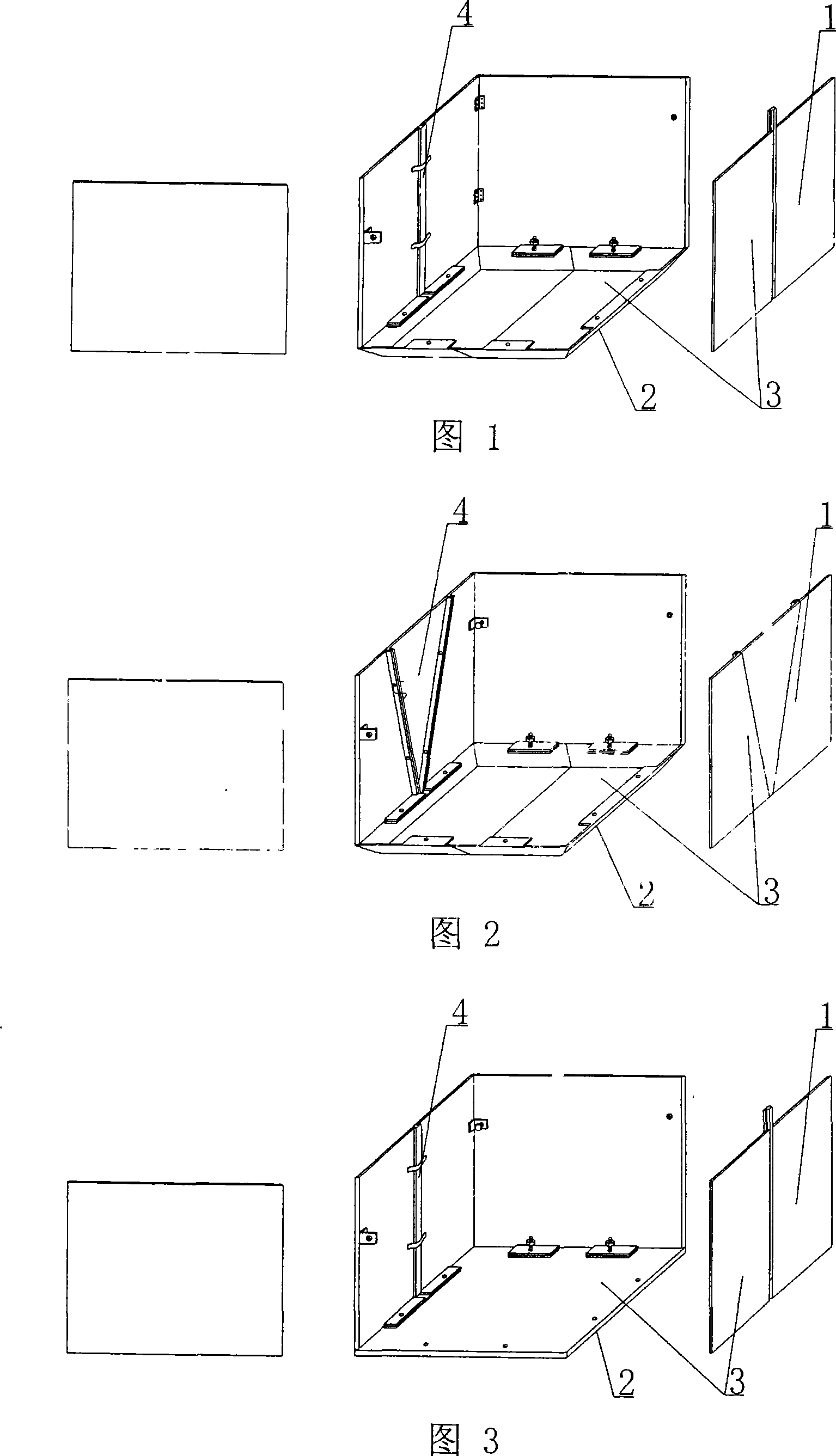
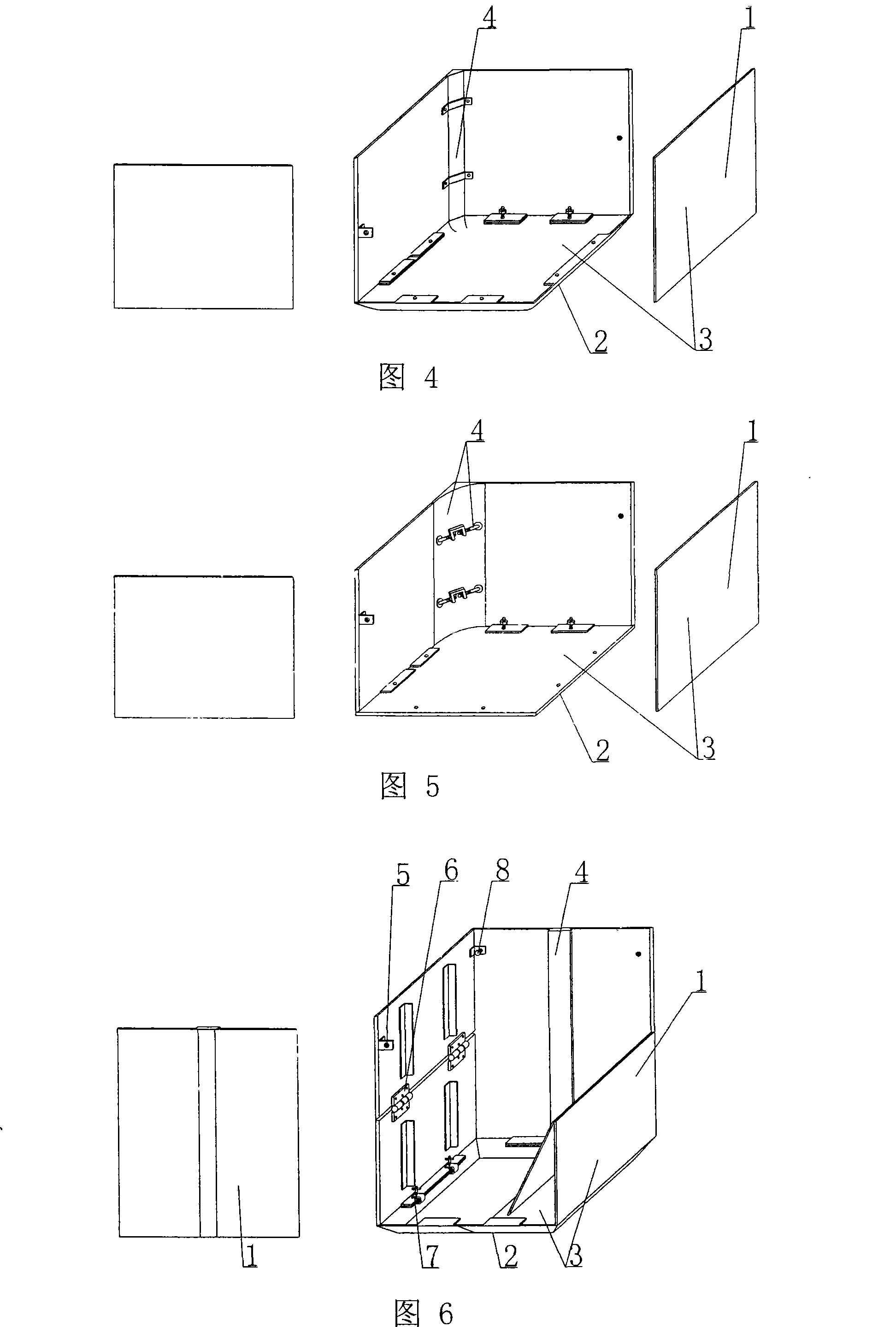
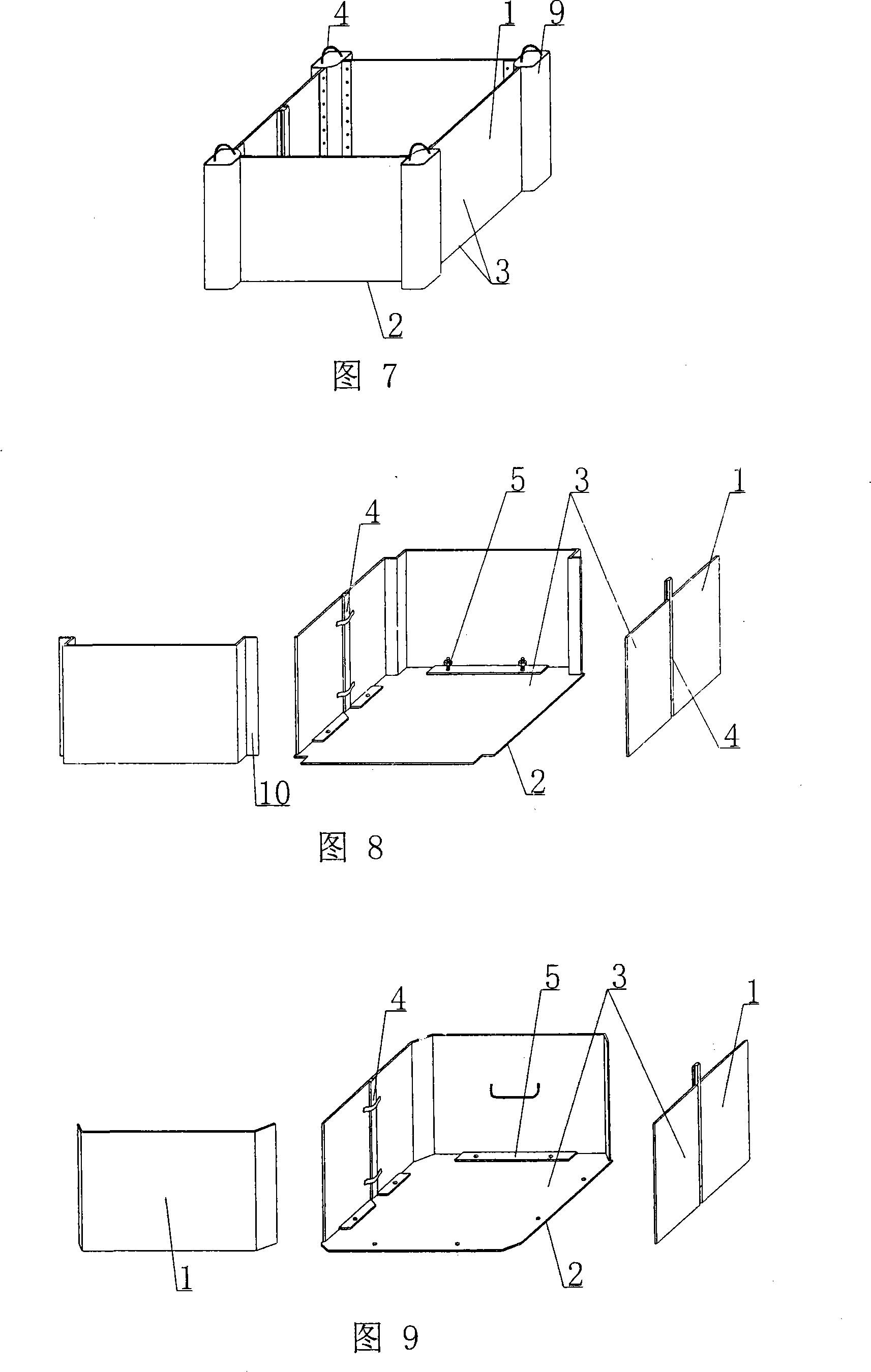
[0062] As shown in the accompanying drawings, the present invention includes a side mold surface 1 and a lower mold surface 2, and the side mold surface 1 and the lower mold surface 2 form a male mold, and is characterized in that the side mold surface 1 and the lower mold surface of the male mold 2 is composed of a template 3, the male mold is composed of a lower mold surface template and four side mold surface templates, at least one structure or device 4 for pulling out and demoulding the template is arranged on the combined template 3, and the pulling out and demoulding of the template The structure or device 4 is arranged in the middle and / or at the corners. Among the accompanying drawings, 1 is the side mold surface, 2 is the lower mold surface, 3 is the template, and 4 is the structure or device 4 for extracting and demoulding. In the following a...


PUM


Abstract

The present invention relates to a form member forming mould. It includes side mould plates and lower mould plate, the side mould plates and lower mould plate are combined together and formed into a male mould. It is characterized by that on the combined mould plates at least one mould plate drawing-out demoulding structure or device is set, said mould plate drawing-out demoulding structure or device can be placed in the middle portion or/and corner portion. Said invention is suitable for manufacturing thin-wall tube or thin-wall box, specially, suitable for manufacturing thin-wall tube with opening or thin-wall box with opening.

Description

[0001] This application is a divisional application of an invention patent application with the filing date of February 27, 2004, the application number of 200410005700.6, and the title of "a mold for molding shell components". (1) Technical field [0002] The invention relates to a mold for molding shell components. (2) Background technology [0003] At present, cast-in-place reinforced concrete hollow slabs, especially the non-core-pulling hole-forming process of cast-in-situ reinforced concrete hollow slabs, are generally filled with thin-walled tubes or thin-walled boxes, which can meet the needs of various hollow slabs for evacuating concrete. The applicant applied for an invention patent with the application number 99115665.X and the title "fiber-reinforced thin-walled pipe (box) for reinforced concrete filling and its manufacturing method" on November 29, 1999, and the application number 99115666.8 , the invention patent titled "fiber-reinforced thin-walled box for fi...

Claims


Application Information

Patent Timeline
IPC IPC(8): B28B7/22B28B7/06B28B7/26B28B7/02
Inventor 邱则有
Owner 湖南邱则有专利战略策划有限公司
Why Eureka
Try Eureka