AI technical title is built by Patsnap AI team. It summarizes the technical point description of the patent document.
A technology of rotary seal and ring seal, which is applied in the direction of engine seal, engine components, mechanical equipment, etc., can solve the problems of complex mechanical seal structure, inconvenient maintenance and inability to solve gas leakage, etc., and achieve important economic and social benefits, Installation, maintenance and replacement are convenient, and it is beneficial to the effect of repair and maintenance
Inactive Publication Date: 2011-04-13
中国船舶重工集团公司第七一二研究所
View PDF0 Cites 0 Cited by
Summary
Abstract
Description
Claims
Application Information
AI Technical Summary
This helps you quickly interpret patents by identifying the three key elements:
Problems solved by technology
Method used
Benefits of technology
Problems solved by technology
The shortcomings of these two types of seals are: in the contact seal, except for the mechanical seal, other types of seals have defects such as large friction loss, short life, inconvenient maintenance, worn shaft diameter, and can only be installed as a whole. The mechanical seal has a complex structure, requires high machining accuracy, occupies more space in the axial direction, and its life is generally only about one year; in the non-contact rotary seal, except for the magnetic fluid seal, other types of seals cannot To solve the problem of gas leakage, the magnetic fluid seal has certain limitations in pressure resistance. It is generally used for low pressure in the rotary shaft seal, not for high pressure; the heat resistance of magnetic fluid is poor, and when its temperature is higher than 90 degrees, it will not Stable state; at present, it is not possible to guarantee the long-term stable dynamic sealing of the rotary shaft for liquids, and it is only limited to sealing gas media
Method used
Image
Click on the blue label to locate the original text in one second.
Reading with bidirectional positioning of images and text.
Examples
Embodiment Construction
[0033] The present invention is further described as follows in conjunction with accompanying drawing and embodiment:
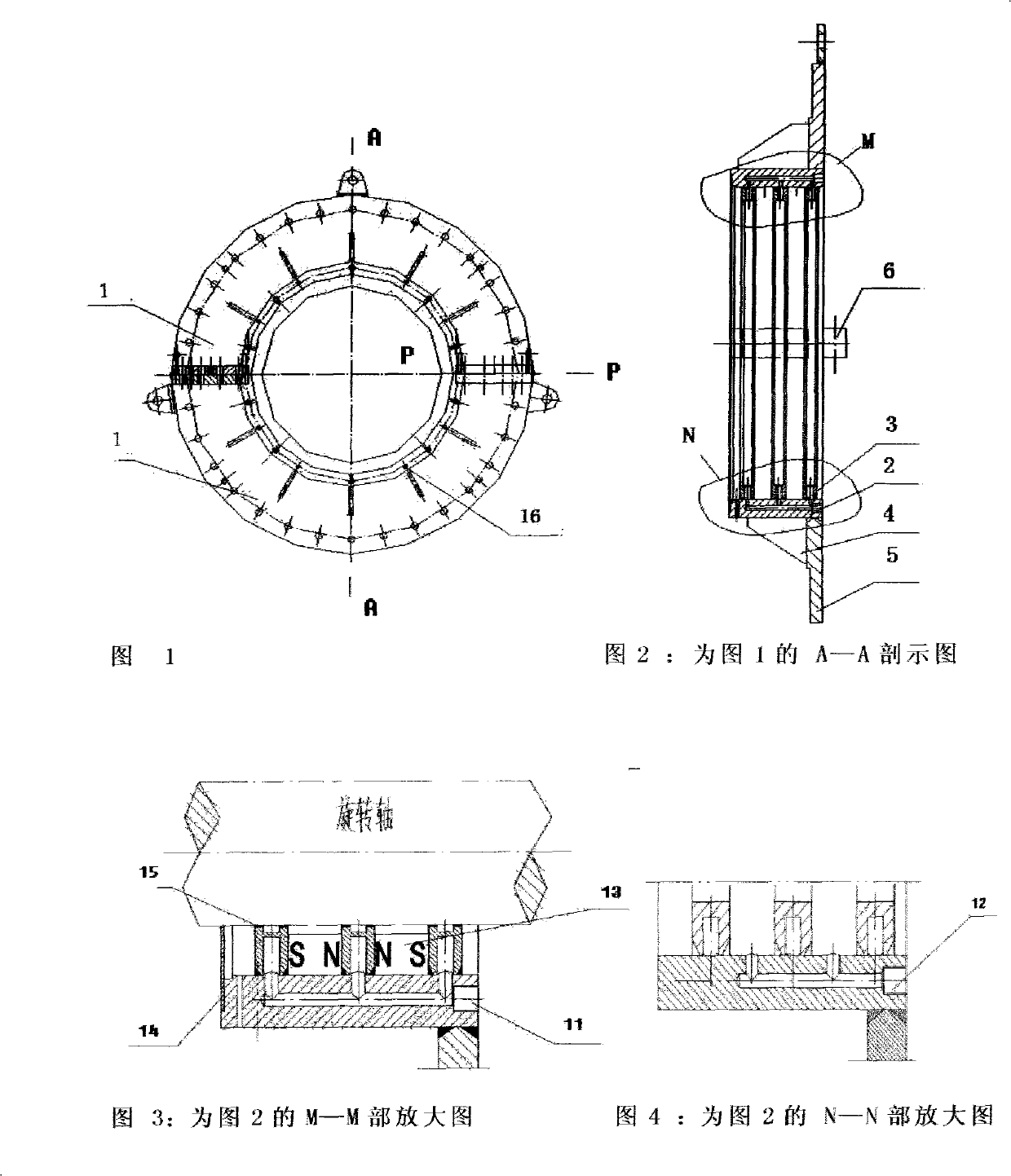
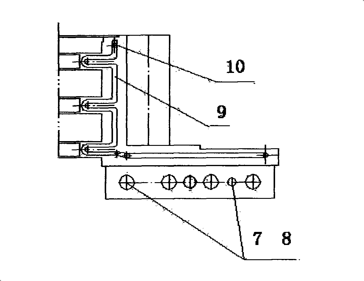
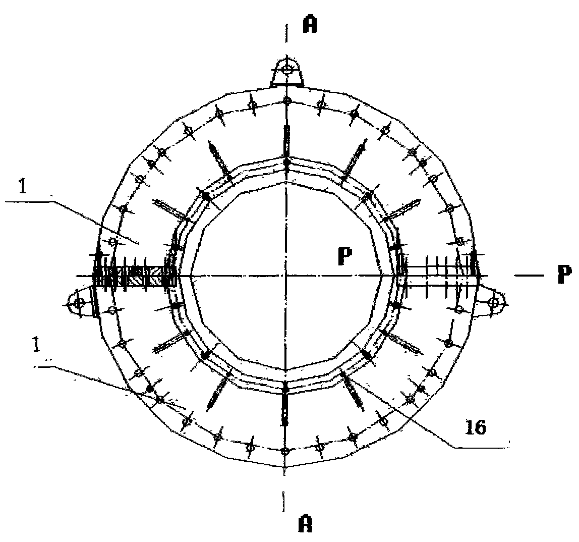
[0034] As shown in Figures 1 to 5, it is a kind of rotary seal, which is composed of two upper and lower half-ring seals 1 connected to form a full-circle ring seal; the half-ring seal 1 has a half-ring base 2, and the half-ring base 2 is set The components include a cooling water jacket 3 , an end cover connecting plate 5 , and a half-ring seal connecting plate 6 for connecting two half-ring seals 1 ; there are cooling circuits and grease filling holes 12 on the half-ring base 2 . The opening angle of the upper and lower half-ring seals 1 is 180°, and each half-ring seal 1 is a welded integral structure; the half-ring base 2 also has ribs 4 for strengthening the connecting plate 5 of the end cover; cooling water jacket 3 , the end cover connecting plate 5, the semi-ring sealing connecting plate 6, and the rib plate 4 are all welded with the semi-ring substra...
PUM
Abstract
The invention relates to a rotating seal which belongs to the field of sealing technology, in particular to a non-contact seal that is especially suitable for being used as the seal of two phase of gas-liquid or a revolving spindle with higher linear velocity. A whole ring-shaped seal is formed by connecting an upper semi-ring seal and a lower semi-ring seal; the semi-ring seals are respectively provided with a semi-ring base body which is provided with a cooling jacket, an end cover connecting plate and a semi-ring seal connecting plate used for connecting the two semi-ring seals; and the semi-ring base body is also provided with a cooling loop and a lipid supplementing hole. The invention has the advantages of greatly reducing the friction and abrasion of the sealing contact surface andavoiding the damage of shaft diameter; due to the distinctive valving structure of the rotating seal, the installation and maintenance are convenient, and the application scope and field can be enlarged; the rotating seal has good sealing performance, no leakage, strong pressure-proof capability and long service life, and can be used for sealing gas and liquid at the same time.
Description
technical field [0001] The invention relates to a rotary seal, which belongs to the technical field of sealing, is a non-contact seal, and is especially suitable for a seal with a relatively high linear velocity, a rotating shaft, and a vapor-liquid two-phase seal. Background technique [0002] In the prior art, the dynamic seals used for rotating shafts include contact seals, including packing seals, expanding ring seals, forming seals, mechanical seals, etc.; and non-contact seals, including labyrinth seals, centrifugal seals, Ferrofluid seals, etc. The shortcomings of these two types of seals are: in the contact seal, except for the mechanical seal, other types of seals have defects such as large friction loss, short life, inconvenient maintenance, worn shaft diameter, and can only be installed as a whole. The mechanical seal has a complex structure, requires high machining accuracy, occupies more space in the axial direction, and its life is generally only about one yea...
Claims
Application Information
Patent Timeline
Application Date:The date an application was filed.
Publication Date:The date a patent or application was officially published.
First Publication Date:The earliest publication date of a patent with the same application number.
Issue Date:Publication date of the patent grant document.
PCT Entry Date:The Entry date of PCT National Phase.
Estimated Expiry Date:The statutory expiry date of a patent right according to the Patent Law, and it is the longest term of protection that the patent right can achieve without the termination of the patent right due to other reasons(Term extension factor has been taken into account ).
Invalid Date:Actual expiry date is based on effective date or publication date of legal transaction data of invalid patent.

