Compressor

A compressor and compressor technology, which is applied in the field of compressors to achieve the effect of being easy to manufacture

Inactive Publication Date: 2014-04-16
CONTINENTAL REIFEN DEUTSCHLAND GMBH
View PDF1 Cites 0 Cited by
  • Summary
  • Abstract
  • Description
  • Claims
  • Application Information

AI Technical Summary

Problems solved by technology

However, for cost reasons, such compressor equipment with a relatively complex structure is only suitable for simple mass-produced devices

Method used


Image

  • Compressor
  • Compressor
  • Compressor

Examples


Embodiment Construction

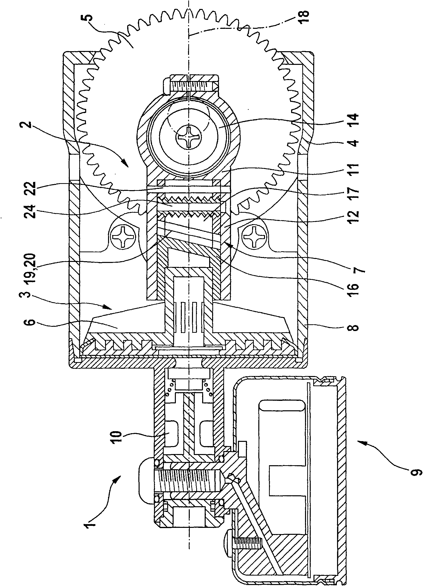
[0046] figure 1 Shown is a schematic diagram of a compressor 1 according to the invention, which shows a cross-sectional view of a partial structure, the compressor comprising a motor not shown in detail here and a piston compressor 3, which is driven by a crankshaft-connecting-rod mechanism 2 to drive. The crankshaft linkage 2 arranged in the crankcase 4 comprises a flywheel 5 and a linkage 7 which is connected on the one hand to the flywheel 5 via a connecting rod journal and on the other hand to the piston 6 . Piston 6 is movable in cylinder 8 , wherein the latter (cylinder) is integrally formed with crankcase 4 and is fastened as one component to the output of the electric motor.

[0047] Control elements and line components not shown in detail here, such as a pressure gauge 9 and an outlet valve 10 here, are arranged on the pressure supply side of the piston compressor.

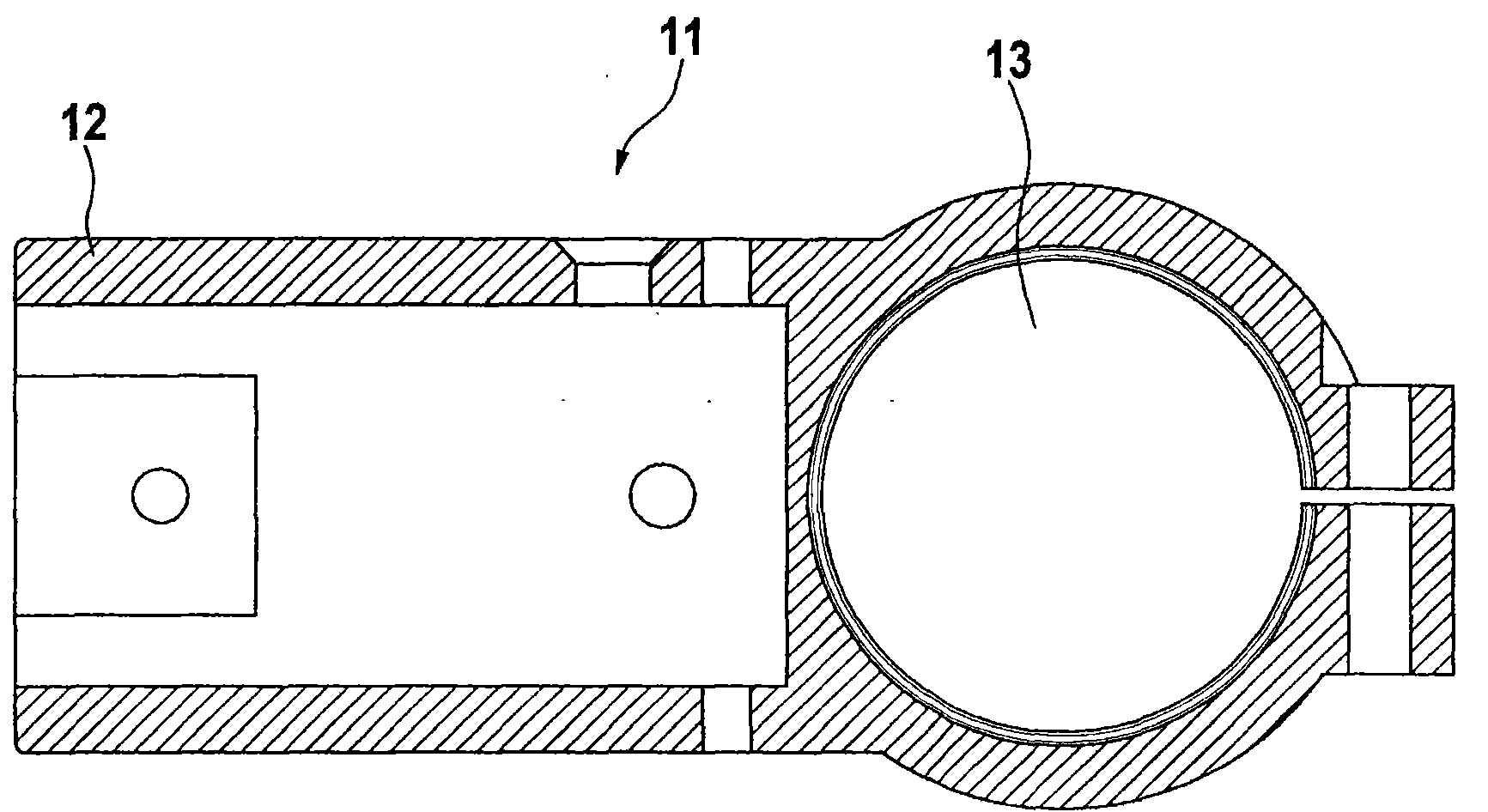
[0048] figure 2 A sectional view of the link 11 connected to the flywheel 5 in the link mechanism...


PUM


Abstract

The compressor (1) has a crank wheel (5) connected with a crankshaft in a torque-proof manner and supported in a crankcase (4). A piston rod (7) is supported with a piston rod bearing (14) on a crank pin of a crankshaft and connected with a piston (6). An upper dead center of the piston is adjusted relative to a cylinder base. The piston rod is formed from a piston rod part (11), which is arranged in a piston rod longitudinal axis (18) by an adjustable sliding block (17) connected with the rod part in a movable manner. A sliding block guide and / or a sliding block mold are made of plastic.

Description

technical field [0001] The present invention relates to a compressor, the compressor includes a motor, and the motor drives a piston compressor through a transmission device, wherein the transmission device is provided with a crankshaft connecting rod mechanism, and the crankshaft connecting rod mechanism drives the piston in the cylinder For reciprocating linear motion. The crankshaft linkage mechanism also includes a flywheel, which is connected to the crankshaft in a torsion-resistant manner, and the flywheel is arranged in the crankcase, and the flywheel is provided with an external gear, and the external gear is connected with the secondary gear of the motor. The driving wheel is meshed; the crankshaft link mechanism also includes a link mechanism, which is arranged on the connecting rod journal of the crankshaft through a link bearing on the one hand and connected to the piston on the other hand. The top dead center of the piston connected to the linkage mechanism is ad...

Claims


Application Information

Patent Timeline
Patent Type & Authority Patents(China)
IPC IPC(8): F04B35/02
CPCF04B35/01F04B53/14F04B35/06
Inventor 赖纳·德特林
Owner CONTINENTAL REIFEN DEUTSCHLAND GMBH
Why Eureka
Try Eureka