Cooling structure of crankcase of directly coupled type air compressor

A technology of air compressor and cooling structure, applied in the direction of liquid variable capacity machinery, mechanical equipment, variable capacity pump components, etc. problem, to achieve the effect of lowering the temperature

Active Publication Date: 2012-08-08
ZHEJIANG HONGYOU AIR COMPRESSOR MFG
View PDF0 Cites 5 Cited by
  • Summary
  • Abstract
  • Description
  • Claims
  • Application Information

AI Technical Summary

Problems solved by technology

However, the above-mentioned traditional cooling method still has defects, and this is that the cooling of the crankcase of the compressor is not in place: on the one hand, at the fixed connection between the crankcase and the motor, there are usually only several ventilators that only rely on natural convection for heat exchange. Slot holes, because no special forced convection cooling measures are taken, the result is that this area becomes a bad area or even a dead area for gas flow, so the heat generated by the stator and rotor of the motor is transferred in a large amount and accumulated in the crankcase. On the box body; on the other hand, the heat generated by the air during the compression process is absorbed by the cylinder block in a large amount, except that part of the heat is taken away by the cooling air, there is still a lot of heat introduced from the connection between the cylinder and the crankcase to the crankcase body
The heat of the above two parts finally makes the base temperature of the crankcase body at a higher level, thus causing the following problems: 1) For oil-lubricated compressors, the high temperature of the crankcase accelerates the storage in the compressor. The oxidation and deterioration process of lubricating oil will inevitably affect the normal operation of the compressor; 2) For oil-free compressors, although sometimes a small fan is installed at the crank pin to cool the connecting rod big head bearing, However, due to the occlusion of the balance weight and the connecting rod shaft, it is difficult to effectively cool down the crankcase body. Shortened life, especially for oil-free compressors with crankcase air intake, the high temperature of the crankcase will also cause the intake air temperature to rise and reduce the volumetric efficiency of the compressor

Method used


Image

  • Cooling structure of crankcase of directly coupled type air compressor
  • Cooling structure of crankcase of directly coupled type air compressor
  • Cooling structure of crankcase of directly coupled type air compressor

Examples


Embodiment Construction

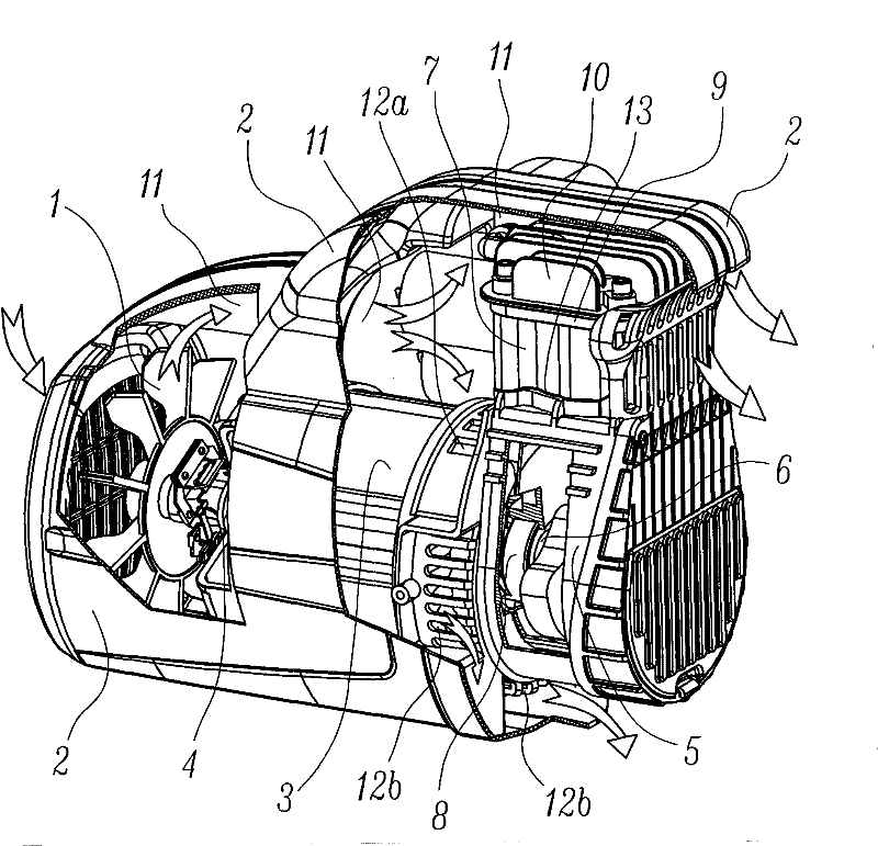
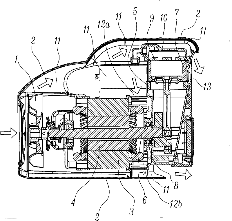
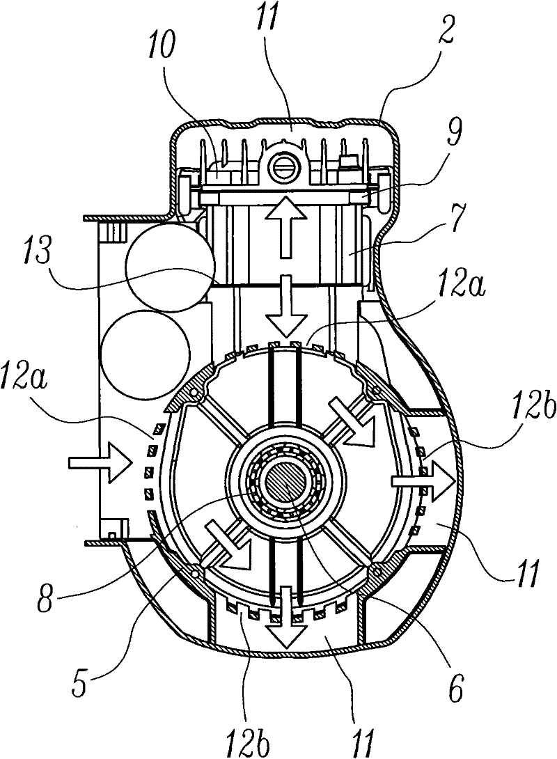
[0018] The present invention will be further described below with specific embodiment: see Figure 1-5 :

[0019] Direct-coupled air compressor crankcase cooling structure, which includes: cooling fan 1, housing 2, motor stator 3, motor rotor 4, crankcase 5, crankshaft 6 and cylinder 7, the motor stator 3 and crankcase 5 Tightly connected, the motor rotor 4 is supported on the bearing seat hole of the crankcase 5 through the crankshaft 6 and the main bearing 8; one end of the cylinder 7 is tightly connected with the crankcase 5, and the other end of the cylinder 7 is connected with a valve seat 9 and The cylinder head 10, wherein the valve seat 9 and the cylinder head 10 can be made in one piece; it should be pointed out that the above-mentioned housing 2 covers the motor stator 3, the crankcase 5, the cylinder 7, the valve seat 9 or the cylinder head 10 in whole or in part. In it, the so-called air passage 11 is formed, and the air passage 11 can be formed by one flow passag...


PUM


Abstract

The invention provides a cooling structure of a crankcase of a directly coupled type air compressor. The cooling structure comprises a cooling fan, a cover shell, a motor stator, a motor rotor, a crankcase and a gas cylinder, wherein the motor stator and the gas cylinder are fixedly connected with the crankcase; a gas inlet and a gas outlet are arranged between the crankcase and the motor stator;the cooling wind generated by the cooling fan is forced to pass through a heat dissipation channel arranged in an area between the motor stator and the crankcase from the gas inlet and then discharged from the gas outlet; and a heat insulating pad is arranged on a joint between the gas cylinder and the crankcase. The invention adopts a forced ventilation cooling structure to allow the cooling wind to cross, laterally pass, penetrate, reflux or crossly pass the area between the motor and the crankcase, so that the heat generated by the motor stator and the motor rotor and the partial heat already absorbed by the crankcase can be effectively brought away from the gas outlet; and because the heat insulating pad is arranged on the joint between the gas cylinder and the crankcase, the heat of the gas cylinder can be effectively avoided from being transferred to the crankcase, so that the temperature of the crankcase is reduced.

Description

technical field [0001] The invention relates to a cooling structure for an air compressor crankcase, in particular to a structure for cooling a direct-connected air compressor crankcase. Background technique [0002] In portable air compressors, a large number of structural solutions of electric motors directly driving the compressors are used. The advantage of this is that the compressors are very compact in structure and small in size, so the direct-coupled structure has become the main model of portable small air compressors. . As we all know, direct-coupled air compressors have three main heat sources, one is the current heat and eddy current heat generated by the rotor and stator of the motor, and the other is the compression heat generated by the compressor during the process of compressing the air. Another is the frictional heat caused by friction. The heat is undoubtedly harmful to the compressor. On the one hand, the heat will cause thermal deformation, thermal st...

Claims


Application Information

Patent Timeline
Patent Type & Authority Patents(China)
IPC IPC(8): F04B39/06
CPCF04B39/066F04B39/0022F04B39/12
Inventor 耿爱农陈君立李辛沫阮勤江
Owner ZHEJIANG HONGYOU AIR COMPRESSOR MFG
Why Eureka
Try Eureka