Cold upsetting forming die of slender bolt

A technology for forming dies and bolts, applied in the direction of bolts, manufacturing tools, threaded fasteners, etc., can solve the problems of inability to return, difficult to process, easy to bend, etc., to achieve shortened length, difficult to bend or break, and lighter weight. Effect

Inactive Publication Date: 2010-12-29
MORGAN HARDWARE KUSN
View PDF6 Cites 3 Cited by
  • Summary
  • Abstract
  • Description
  • Claims
  • Application Information

AI Technical Summary

Problems solved by technology

[0003] like figure 1 Shown: the slender bolt cold heading forming die includes: a female mold 1, a forming inter-module block 2 and a feed rod 3, wherein the forming inter-module block 2 is located at the rear of the female mold 1, and its central through hole is connected to the female mold 1 Cavity docking, feeding rod 3 is set in the cavity of the mother mold 1 and the through hole of the forming module block 2, and the rear part of the feeding rod 3 is also provided with a bolt passing mechanism, which includes a large back screw 4. The rear moving connecting rod 5 and the power source, etc. The rear moving connecting rod 5 is located at the center of the rear supporting large screw 4, and it is driven by the power source. The elongated bolt cold heading forming mold with this structure has a long mother mold 1, The feed rod 3 does not have any support. When the diameter of the bolt 0 exceeds 300mm, the feed rod 3 will easily bend and break when it is working, so that the material cannot be returned. Rod 5 also needs to be designed to be very long and heavy, which is not easy to process

Method used


Image

  • Cold upsetting forming die of slender bolt
  • Cold upsetting forming die of slender bolt
  • Cold upsetting forming die of slender bolt

Examples


specific Embodiment approach

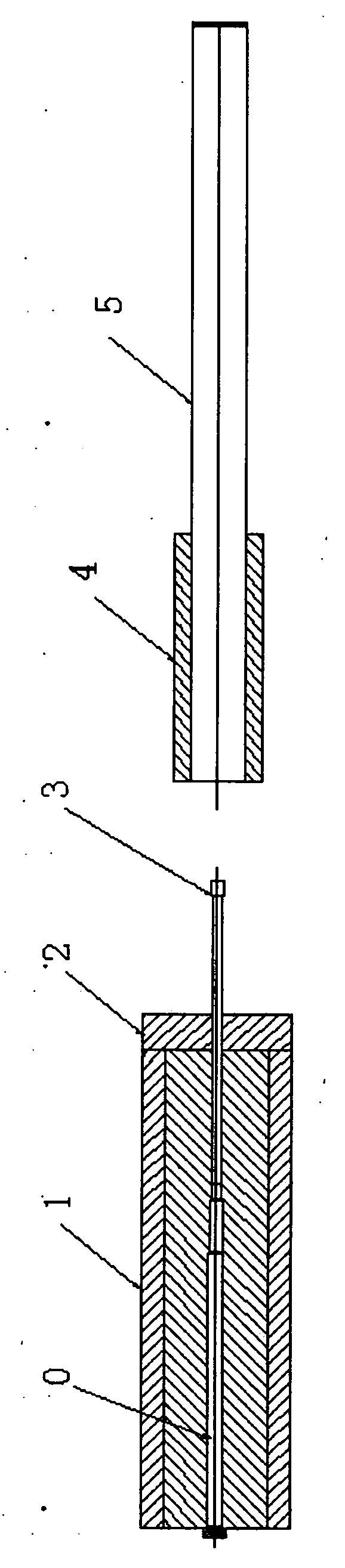
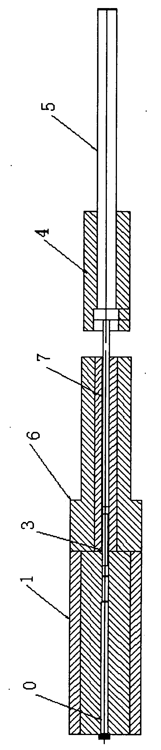
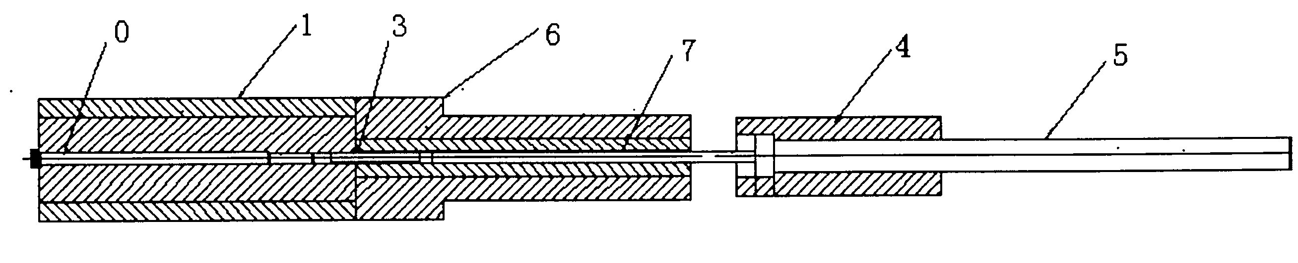
[0015] figure 2 It is a structural schematic diagram of an embodiment of the present invention.

[0016] like figure 2 Shown: a slender bolt cold heading forming mold, including a master mold 1, a feeding rod 3, a large rear support screw 4 and a rear moving connecting rod 5. One end of the feeding rod 3 is set in the cavity of the female mold 1, and its The rear part is the back supporting large screw 4, and the rear moving connecting rod 5 is located at the center of the rear supporting large screw 4. It is characterized in that a safety protection tube 6 is also arranged at the rear of the master mold 1, and the safety protection tube 6 is set in the through The other end of the material rod 3, and the central hole of the safety protection tube 6 corresponds to the cavity of the master mold, and the head of the rear moving connecting rod 5 is also connected with a mold opening lever 7, and the front end of the mold opening lever 7 extends into to the center hole of the ...


PUM


Abstract

The invention discloses a cold upsetting forming die of a slender bolt. The forming die comprises a female die, a dredging bar, a backrack big screw and a back movable connection rod; one end of the dredging bar is arranged in the cavity of the female die; the back part of the female die is provided with the backrack big screw; and the back movable connection rod is arranged at the center of the backrack big screw. The invention is characterized in that the back of the female die is also provided with a safety protection pipe; the safety protection pipe is sleeved on the other end of the dredging bar; and the central hole of the safety protection pipe is opposite to the cavity of the female die. As the safety protection pipe is arranged on the periphery of the dredging bar and the central hole of the safety protection pipe is opposite to the cavity of the female die, the length of the female die can be set to be shorter; as the external diameter of the dredging bar is increased and the dredging bar is supported, the dredging bar is difficult to bend or crack in the driving or retreating process and the work efficiency can not be influenced; and as a starting tringle is added on the front part of the back movable connection rod, the length of the back movable connection rod can be shortened, the weight can be lightened and the defect that the back movable connection rod is difficult to process can be overcome.

Description

technical field [0001] The invention relates to a cold heading forming die, in particular to a cold heading forming die for slender bolts, belonging to the technical field of precision machinery manufacturing. Background technique [0002] figure 1 It is a schematic diagram of the traditional slender bolt cold heading forming die. [0003] like figure 1 Shown: the slender bolt cold heading forming die includes: a female mold 1, a forming inter-module block 2 and a feed rod 3, wherein the forming inter-module block 2 is located at the rear of the female mold 1, and its central through hole is connected to the female mold 1 Cavity docking, feeding rod 3 is set in the cavity of the mother mold 1 and the through hole of the forming module block 2, and the rear part of the feeding rod 3 is also provided with a bolt passing mechanism, which includes a large back screw 4. The rear moving connecting rod 5 and the power source, etc. The rear moving connecting rod 5 is located at t...

Claims


Application Information

Patent Timeline
Patent Type & Authority Applications(China)
IPC IPC(8): B21J13/02B21K1/44
Inventor 涂春旺林茂森
Owner MORGAN HARDWARE KUSN
Why Eureka
Try Eureka