Hot water appliance

A technology of hot water equipment and water tank, which is applied in the field of hot water equipment to achieve the effect of improving assembly scheme and improving energy utilization

Inactive Publication Date: 2011-10-12
BSH BOSCH & SIEMENS HAUSGERAETE GMBH
View PDF6 Cites 0 Cited by
  • Summary
  • Abstract
  • Description
  • Claims
  • Application Information

AI Technical Summary

Problems solved by technology

This has the disadvantage that the size of th...

Method used


Image

  • Hot water appliance
  • Hot water appliance
  • Hot water appliance

Examples


Embodiment Construction

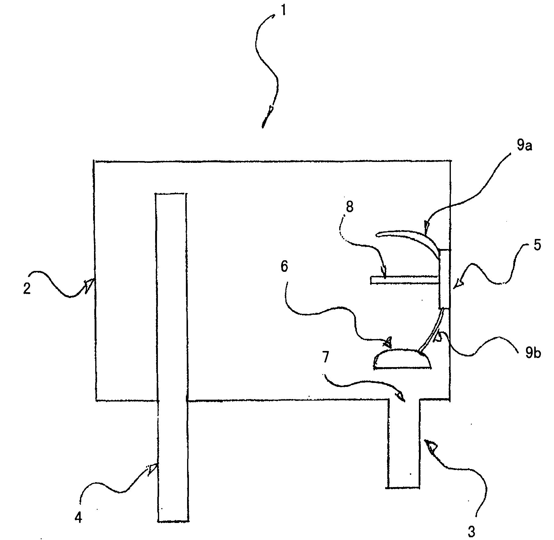
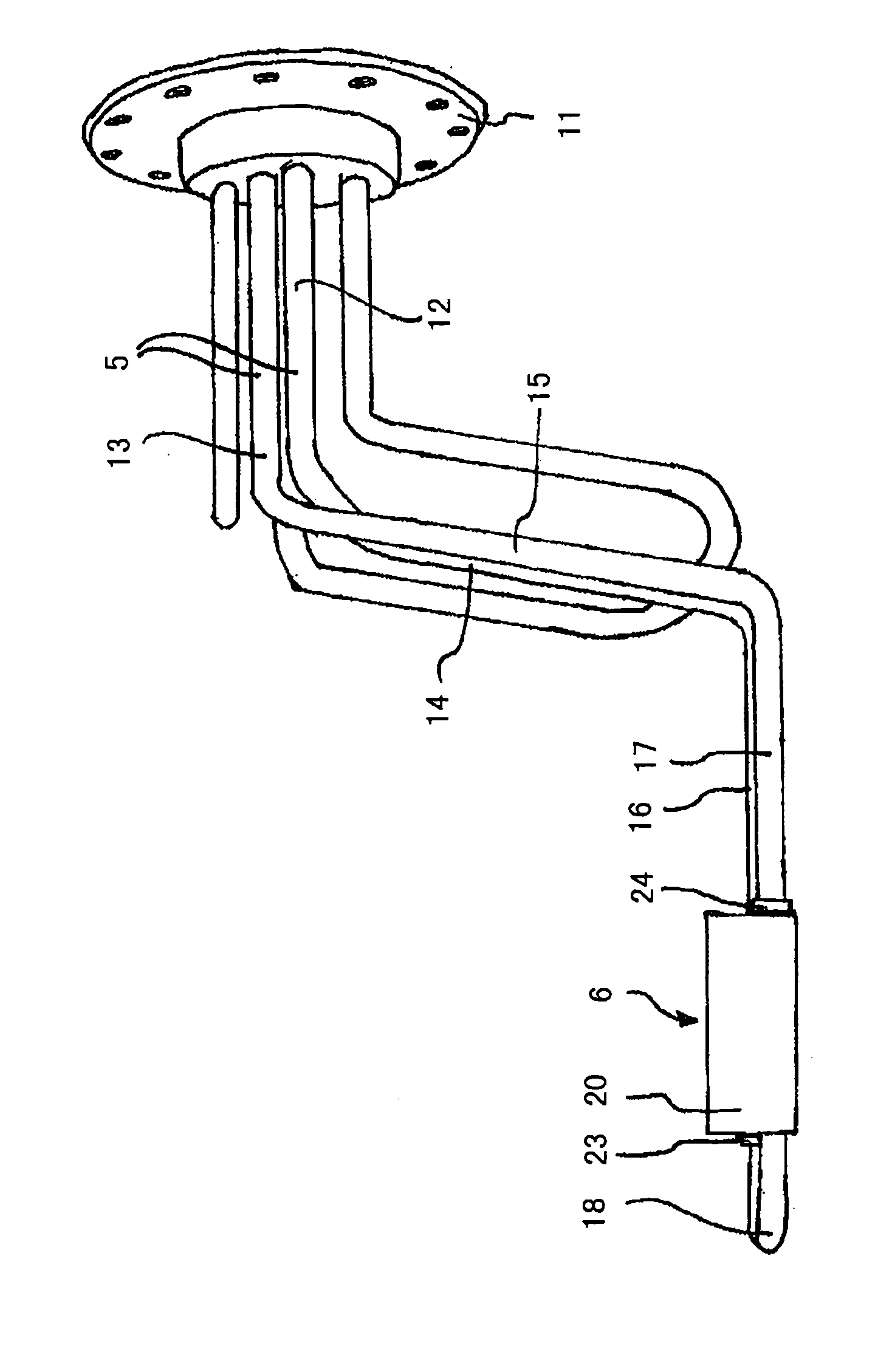
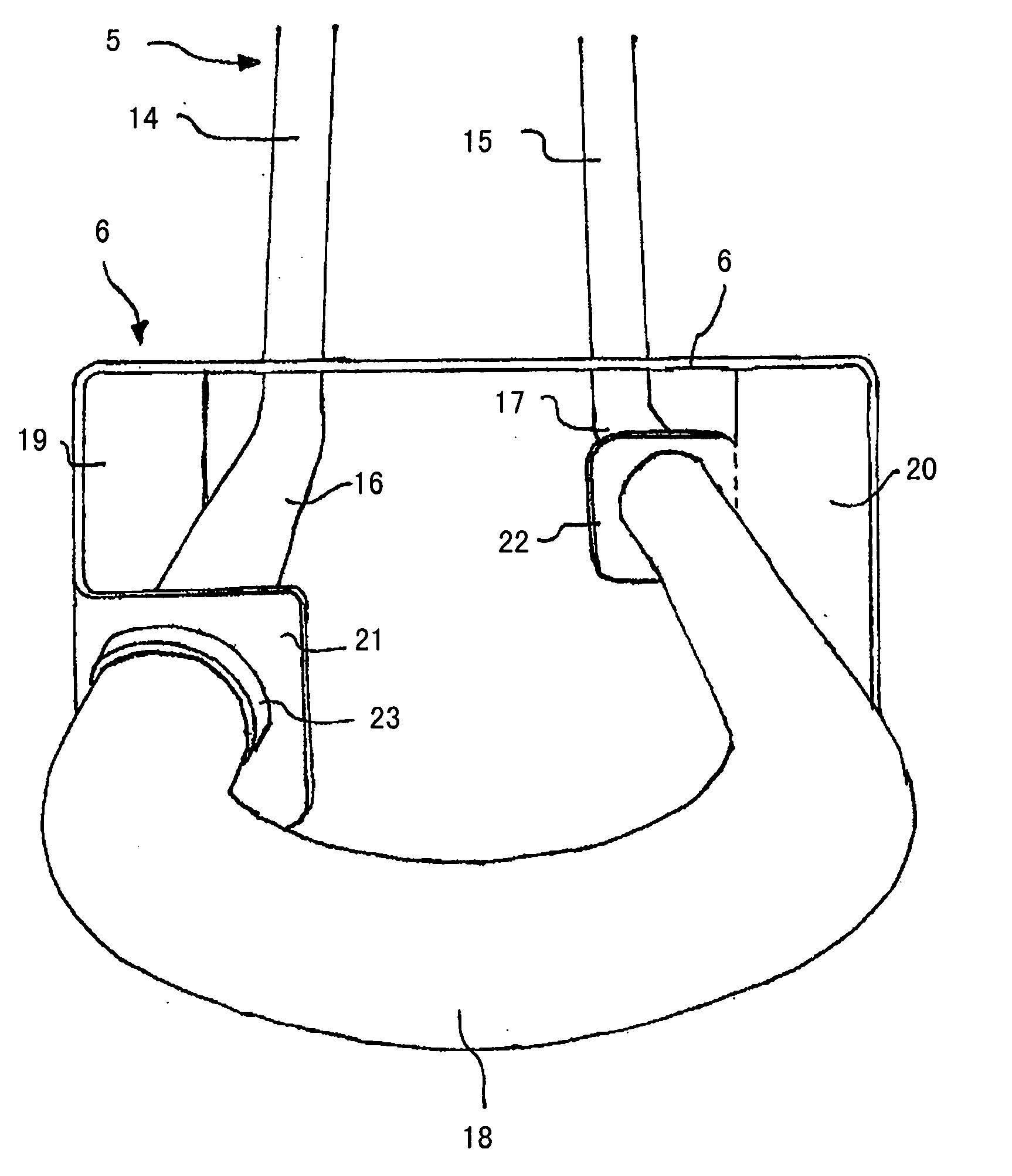
[0029] figure 1Shown is a hot water installation 1 comprising a water tank 2 , a water inlet 3 , a water outlet 4 , a heating element 5 and means 6 for at least partially covering an inflow point 7 of the water inlet. The water inlet 3 is arranged at the lower end of the water tank 2 . The water outlet 4 is placed at a very high position, that is, a little bit below the upper wall of the water tank. This has the advantage that the water with the highest temperature that accumulates in the water tank 2 in the upper region of the water tank flows out through the water outlet 4 . In this case, the heating element 5 is connected to means 6 for at least partially covering the inflow point 7 of the water inlet 3 . The means 6 for at least partially covering the inflow point 7 are connected to the heating element 5 via a heating wire 9 a. The heating element 5 here comprises a base plate 10 , two heating wires 9 a and 9 b and a sensor 8 . The inflowing water is at least partially...


PUM


Abstract

The invention relates to a hot water appliance (1) at least comprising a water tank (2), a water supply pipe (3), a water discharge pipe (4), a heating element (5), and a means (6) for at least partly covering an inlet point (7) of the water supply pipe (3). The invention is characterized in that the heating element (5) is connected to the means (6) for at least partly covering the inlet point (7) of the water supply pipe (3), said means (6) for at least partly covering the inlet point (7) of the water supply pipe (3) deflecting at least some of the water to the bottom of the water tank (2).

Description

technical field [0001] The invention relates to a hot water device comprising at least a hot water tank, a water inlet, a water outlet, a heating element and a mechanism for at least partially covering the water inlet. Background technique [0002] Hot water installations with a water tank for heating water are widely known in the prior art. In such devices, a water inlet is usually provided on the bottom side of the water tank through which cold water can flow into the water tank. Water outlets are usually provided on the upper side of the water tank, through which water can leave the water tank and be directed to the user. Since hot water accumulates on the upper side of the tank, it is ensured by such a device that the water at the water outlet has the highest temperature. If now cold water flows into the water tank after a large amount of hot water has been taken, it sometimes takes a long time until hot water can be supplied again. If the cold water flows directly in...

Claims


Application Information

Patent Timeline
IPC IPC(8): F24H9/18F24H9/12
CPCF24H1/202F24H9/0015
Inventor B·施勒德
Owner BSH BOSCH & SIEMENS HAUSGERAETE GMBH
Why Eureka
Try Eureka