

Illumination threshing machine
A thresher, LED lighting technology, applied in threshing equipment, agricultural machinery and implements, applications, etc., can solve problems such as rush harvesting
Inactive Publication Date: 2012-04-25
陈达平
View PDF0 Cites 0 Cited by
- Summary
- Abstract
- Description
- Claims
- Application Information
AI Technical Summary
Problems solved by technology
[0003] The purpose of this invention is to provide a lighting thresher, which solves the lighting problem of the thresher in the field at night
[0005] Through the lighting provided by LED lighting, it solves the lighting problem of production rush at night or when the light is insufficient
Method used
View moreImage
Smart ImageViewing Examples

Examples
Embodiment Construction
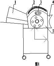
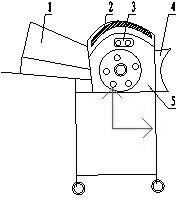
[0009] Combine below figure 1 Illustrate the concrete situation of the present invention: in figure 1 In the thresher body (5), install an LED light (2) on the top between the feed port (1) and the grain outlet (4), and install an LED light switch ( 3).
[0010] The lighting provided by the LED lighting lamp (2) solves the lighting problem of rush harvesting at night or when the light is insufficient.
Login to View More PUM
 Abstract
The invention relates to an illumination threshing machine. According to the invention, the illumination problem that rush harvesting is generated at night or when light is inadequate is solved through installing an LED (light-emitting diode) illuminating lamp on the top of the illumination threshing machine. The illumination threshing machine is suitable for installation of a small-size threshing machine.
Description
technical field [0001] The invention belongs to the technical field of agricultural production and is an illuminated thresher. The LED lighting lamp installed on the top of the thresher solves the problem of lighting the thresher at night in the field, which is beneficial to rush harvesting and is suitable for the installation of small threshers. Background technique [0002] The current small threshers have no lighting device, which is unfavorable for night production and harvesting, and it is inconvenient to move with the installed living lighting, which brings safety hazards to operators. Contents of the invention [0003] The object of the present invention is to provide an illuminating thresher, which solves the lighting problem of the thresher at night in the field. [0004] The described purpose of the present invention is achieved like this: figure 1 In the process, an LED light is installed on the top between the feed inlet and the grain outlet of the thresher ma...
Claims
Login to View More Application Information
Patent Timeline
 Patent Type & AuthorityApplications(China)
IPC IPC(8): A01F12/00
Inventor陈达平
Owner陈达平