Electrical drive unit for a motor vehicle

An electric drive unit, vehicle technology, applied in the direction of electrical components, electric components, electromechanical devices, etc., can solve problems such as damage

Inactive Publication Date: 2012-08-22
SCHAEFFLER TECH AG & CO KG
View PDF4 Cites 0 Cited by
  • Summary
  • Abstract
  • Description
  • Claims
  • Application Information

AI Technical Summary

Problems solved by technology

These impurities or liquids can cause damage on the hub drive itself and on the effective sealing surfaces of the seals of the hub drive

Method used


Image

  • Electrical drive unit for a motor vehicle
  • Electrical drive unit for a motor vehicle
  • Electrical drive unit for a motor vehicle

Examples


Embodiment Construction

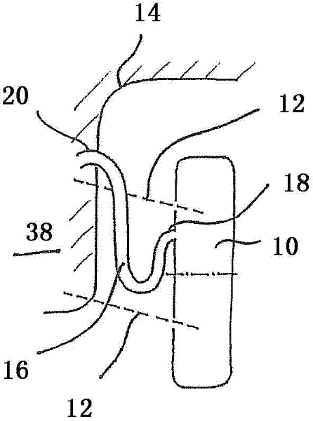
[0026] figure 1A first embodiment of an electric drive unit according to the invention is schematically shown with a hub drive arranged on a wheel 10 , not shown here, wherein the wheel 10 is fastened via a wheel suspension 12 to a wheel arch 14 of the vehicle. In order to be able to equalize the pressure between the interior of the wheel hub drive, which is sealed off by a seal (not shown here) and the environment, a ventilation device with an air duct 16 is provided. The air duct 16 is designed here in the form of a hose, which is guided from the interior of the wheel hub drive inside the wheel 10 via the wheel arch 14 into the interior 38 of the vehicle. In this case, a first end section 18 of the air line 16 leads into the interior of the wheel hub drive and a second end section 20 of the air line 16 , which is opposite the first end section 18 , leads. into the interior space 38 of the vehicle. The ventilation here takes place toward the vehicle interior 38 .

[0027] ...


PUM


Abstract

The invention relates to an electrical drive unit for a motor vehicle, said drive unit comprising a wheel hub drive that drives a vehicle wheel. Said wheel hub drive has a sealing element which is affected by friction and by means of which the interior of the wheel hub drive is sealed off from the surroundings in an airtight manner. According to the invention, a ventilation device is provided by means of which a pressure difference between the prevailing air pressure in the interior of the wheel hub drive and the prevailing air pressure of the surrounding air can be compensated by displacing volumes of air.

Description

technical field [0001] The invention relates to an electric drive unit for a vehicle with a hub drive, in particular a hub motor, which drives the wheels. Background technique [0002] In order for an electric drive unit with a wheel hub drive to comply with the requirements prevailing in the vehicle industry with regard to service life, the wheel hub drive must have a corresponding seal. What is problematic in this case is the fact that temperatures between -30° C. and +50° C. can occur in the interior of the wheel hub drive, depending on the season of use, the weather and the operating state. If the wheel hub drive is hermetically sealed from the outside using conventional seals, during operation of the wheel hub drive a sharply rising internal pressure builds up in the interior of the wheel hub drive due to heat, which can lead to The air contained in the drive lifts the sealing lip for sealing the provided seal and can cause an at least partial pressure equalization out...

Claims


Application Information

Patent Timeline
Patent Type & Authority Applications(China)
IPC IPC(8): H02K5/124H02K5/10
CPCH02K5/124H02K5/10
Inventor 拉斐尔·费舍尔米夏埃尔·伯格纳
Owner SCHAEFFLER TECH AG & CO KG
Why Eureka
Try Eureka