Lifting handle

A handle and handle base technology, applied in the direction of wing leaf handles, applications, door/window accessories, etc., can solve the problems of insignificant buffering effect, inability to fully return the handle, and inability to meet the needs of consumers.

Active Publication Date: 2014-06-11
温州市红鹰箱包配件有限公司
View PDF7 Cites 0 Cited by
  • Summary
  • Abstract
  • Description
  • Claims
  • Application Information

AI Technical Summary

Problems solved by technology

[0002] Existing handles, whether they are handles on bags, safety rails on cars, or handles on doors, need to be fixed to the bags or the side walls or door panels of cars when not in use in order to be beautiful and not occupy space. In fact, this requires the handle with automatic return and fit function. The existing handles with automatic return and fit function are relatively complicated in structure, and in order to cooperate with the function of automatic return and fit, they will also be equipped with damping and buffering functions. So that the handle will not hit the side wall or door panel of the luggage or the car vigorously when the handle is automatically returned. The existing handle with this damping and buffering function has a very complicated structure, and some handles with large damping force There is a defect that it cannot be fully returned. If the damping force is too small, the buffering effect will not be obvious, which cannot meet the needs of consumers.

Method used


Image

  • Lifting handle
  • Lifting handle
  • Lifting handle

Examples


Embodiment Construction

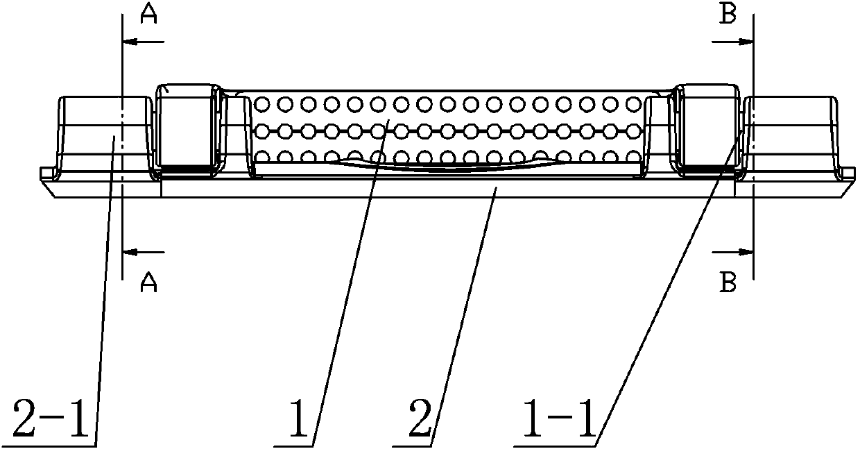
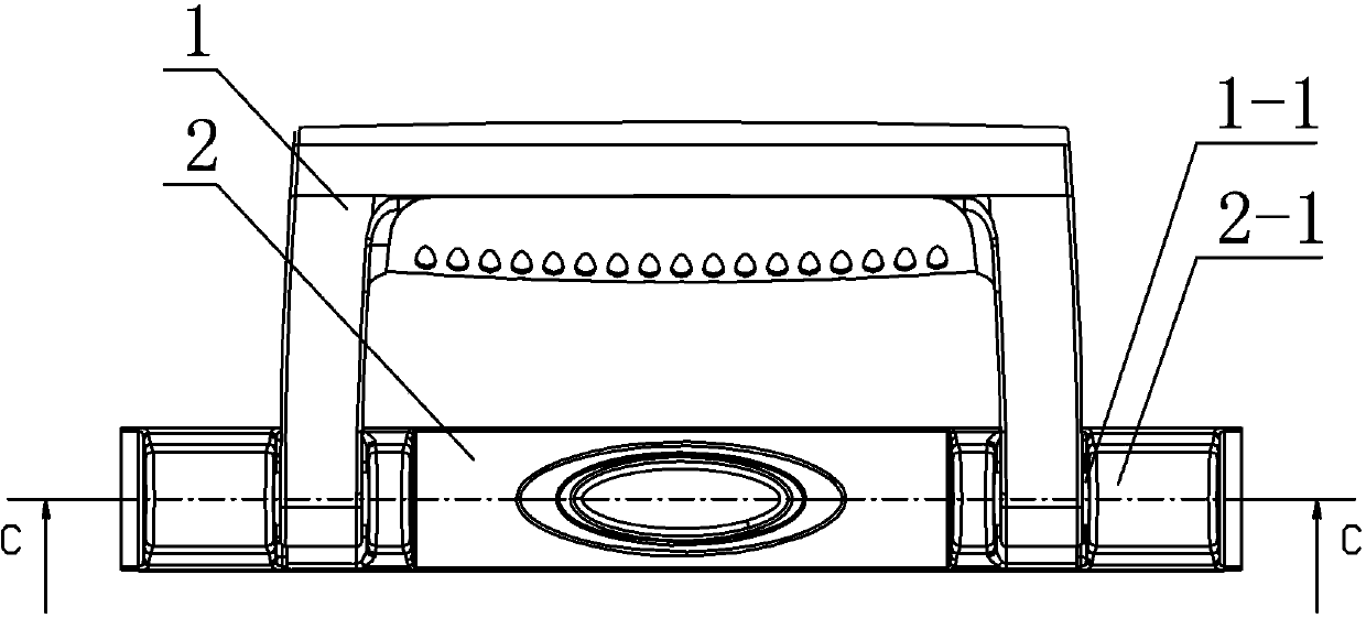
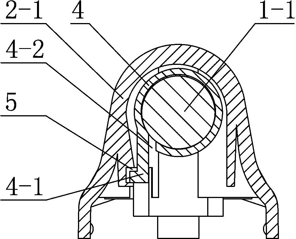
[0016] like figure 1 , figure 2 , image 3 , Figure 4 , Figure 5 , Image 6 , Figure 7 , Figure 8 , Figure 9 As shown, the specific embodiment provided by the present invention is a handle, including a handle 1 and a handle base 2, the lower end of the handle 1 is provided with a connecting column 1-1, the handle base 2 is provided with a connecting sleeve 2-1, and the connecting column 1 -1 cooperates with the connecting sleeve 2-1 to realize the rotatable connection between the lower end of the handle 1 and the handle seat 2, which is characterized in that: the connecting column 1-1 of the handle 1 is provided with a return spring 3, and the return spring 3 is located at the handle 1 connection Between the column 1-1 and the connecting sleeve 2-1 of the handle seat 2, and the return spring 3 provides the elastic force for the handle 1 to fit back, and the other side of the handle 1 is connected to the column 1-1 and the connecting sleeve 2-1 of the handle seat 2...


PUM


Abstract

The invention relates to a lifting handle, which comprises a handle and a handle base, wherein the lower end of the handle is provided with connecting columns; connecting sleeves are arranged on the handle base; the connecting columns are matched with the connecting sleeves, so that the lower end of the handle is connected with the handle base in a rotational mode; return springs are positioned between the connecting columns of the handle and the connecting sleeves of the handle base and are used for providing elastic force for the fit return of the handle; a damping sleeve is arranged between the other side of each of the connecting columns of the handle and the connecting sleeves of the handle base; damping grease is arranged between the damping sleeves and the connecting columns; positioning blocks are arranged on the damping sleeves; positioning grooves are formed on the connecting sleeves; the positioning blocks of the damping sleeves are matched with the positioning grooves of the connecting sleeves; the damping sleeves are provided with gaps; and when the handle is pulled up, the rotation direction of the connecting columns corresponding to the gaps is consistent with that of the stretching of the gaps. The lifting handle has the characteristics of simple structure, good return effect and good damping and buffering effect.

Description

technical field [0001] The invention relates to a handle, in particular to a handle with automatic return and buffer function. Background technique [0002] Existing handles, whether they are handles on bags, safety rails on cars, or handles on doors, need to be fixed to the bags or the side walls or door panels of cars when not in use in order to be beautiful and not occupy space. In fact, this requires the handle with automatic return and fit function. The existing handles with automatic return and fit function are relatively complicated in structure, and in order to cooperate with the function of automatic return and fit, they will also be equipped with damping and buffering functions. So that the handle will not hit the side wall or door panel of the luggage or the car vigorously when the handle is automatically returned. The existing handle with this damping and buffering function has a very complicated structure, and some handles with large damping force There is a de...

Claims


Application Information

Patent Timeline
Patent Type & Authority Patents(China)
IPC IPC(8): A45C13/26E05B7/00B60N3/02
Inventor 陈宏伟
Owner 温州市红鹰箱包配件有限公司
Why Eureka
Try Eureka