Marine bacteria diversity fluorescence detection system

A technology for fluorescence detection and marine bacteria, applied in fluorescence/phosphorescence, material excitation analysis, etc., can solve problems affecting the accuracy of marine bacteria research, changes in parameters such as light and oxygen content, and loss of activity of marine bacteria. The ability of continuous operation under water, low cost of use and maintenance, and the effect of improving work efficiency and detection accuracy

Inactive Publication Date: 2018-01-19
南通鼎盛海洋科技有限公司
0 Cites 0 Cited by

AI-Extracted Technical Summary

Problems solved by technology

[0002] At present, in research activities on marine bacteria, special sampling equipment is often used to sample seawater that is not deep enough, and then transfer the seawater sample to the detection equipment for detection operations. Although this detection method can meet the needs of detection operations to a certain extent, However, during the detection process, it was found that when the seawater samples were collected from the ocean and tested by the detection equipment, the parameters such as temperature, pressure, light and oxygen content of the sample seawater would undergo serious changes, resulting in a large num...

Abstract

The invention relates to a marine bacteria diversity fluorescence detection system, which comprises a bearing substrate, a fluorescence detection device, a light transmission protection cover and a light shielding protection cover, wherein at least one fluorescence detection device is embedded on the outer surface of the bearing substrate and is slidably connected to the outer surface of the bearing substrate through a sliding rail, the sliding rail circles the axial line of the bearing substrate to form a closed ring-like structure, the bearing substrate outer surface corresponding to the fluorescence detection device is provided with a layer of the light transmission protection cover and a layer of the light shielding protection cover, at least two separation plates are arranged in the bearing substrate, the bearing substrate is sequentially divided into a control cavity, a detection cavity and a power cavity from front to rear by the separation plates, and the fluorescence detectiondevice is positioned in the detection cavity. According to the present invention, the marine bacteria diversity fluorescence detection system can effectively meet the on-site continuous fluorescencedetection of marine bacteria in different marine environments, and further has advantages of simple equipment structure, low use cost, low maintenance cost, convenient transportation and carrying, andhigh automation operation degree.

Application Domain

Fluorescence/phosphorescence

Technology Topic

FluorescenceEngineering +4

Image

  • Marine bacteria diversity fluorescence detection system

Examples

  • Experimental program(1)

Example Embodiment

[0014] In order to make the technical means, creative features, objectives and effects achieved by the present invention easy to understand, the present invention will be further explained below in conjunction with specific embodiments.
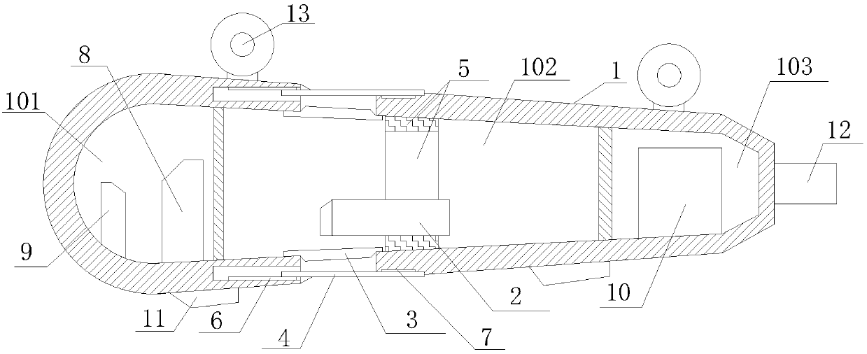
[0015] Such as figure 1 The described fluorescence detection system for marine bacterial diversity includes a carrier substrate 1, a fluorescence detection device 2, a light-transmitting protective cover 3, and a light-shielding protective cover 4, wherein at least one fluorescence detection device 2 is embedded on the outer surface of the carrier substrate 1 and The slide rail 5 is slidably connected to the outer surface of the carrier substrate 1. The slide rail 5 surrounds the axis of the carrier substrate 1 in a closed ring structure. The outer surface of the carrier substrate 1 corresponding to the fluorescence detection device 2 is provided with a transparent protective cover 3 and a layer The light-shielding protective cover 4, and the light-transmitting protective cover 3 and the light-shielding protective cover 4 are distributed parallel to each other and are both distributed perpendicularly to the optical axis of the fluorescence detection device 2, wherein the light-transmitting protective cover 3 is connected to the inner surface of the carrier substrate 1 and is connected to the carrier substrate 1 A closed cavity structure is formed. The end of the light shield 4 is embedded in the side surface of the carrier base 1 and is slidably connected to the carrier base 1 through the driving slide rail 6, and the front end of the light shield 4 is slidably connected to the outer surface of the carrier base 1 through the slide groove 7. The carrier substrate 1 is a closed cavity structure, the axis of which is parallel to the horizontal plane, at least two partitions 7 are arranged in the carrier substrate 1, and the carrier substrate 1 is divided into a control cavity 101 and a detection cavity 102 from front to back by the partitions 7 And the power cavity 103, where the fluorescence detection device 2 is located in the detection cavity 102, the control cavity 101 is equipped with a control circuit 8 and a communication circuit 9, the power cavity 103 is equipped with a driving power supply 10, and the control circuit 8 in the control cavity 101 communicates with The circuit 9, the fluorescence detection device 2, and the driving power supply 10 are electrically connected.
[0016] In this embodiment, the carrier substrate 1 is a closed cavity structure with a capsule-shaped, water-drop-shaped, and shuttle-shaped structure in axial section.
[0017] In this embodiment, at least two baffles 11 are provided on the outer surface of the carrier base 1, and the baffles 11 and the outer surface of the carrier base 1 are hinged by a turntable mechanism, and are distributed on the carrier base 1 axis-symmetrically. The outer surface of the substrate 1.
[0018] In this embodiment, an underwater propeller 12 is additionally provided on the outer surface of the carrier substrate 1. The underwater propeller 12 is electrically connected to the control circuit 8 and the driving power source 10, and the axis of the underwater propeller 12 is connected to the carrier The axis of the base 1 is distributed in parallel.
[0019] In this embodiment, at least two lifting rings 13 are uniformly distributed along the axis direction on the upper surface of the supporting base 1.
[0020] In this embodiment, when there are two or more fluorescence detection devices 2, the fluorescence detection devices 2 on the same slide rail 5 are evenly distributed around the axis of the carrier substrate 1 and distributed on different slide rails 5. The optical axes of the fluorescent detection devices 2 above are distributed in two planes parallel to each other.
[0021] In the specific implementation of the present invention, the carrying substrate is first connected with the hoisting equipment, and then the detection substrate is lowered into the marine environment at a specified depth through the hoisting equipment, and then the light shielding cover is opened, so that the fluorescence detection device can pass through the transparent shield The bacteria in the marine environment around the substrate are subjected to fluorescence detection. When performing fluorescence detection, the fluorescence detection device can rotate 0-360° around the axis of the bearing substrate through the slide rail. On the one hand, it can meet the needs of comprehensive detection of the surrounding environment of the bearing substrate. On the other hand, it meets the need for continuous detection of a specific target.
[0022] In addition, during the inspection operation, the working position of the supporting substrate under water can be adjusted in a small range through the deflector and the underwater thruster to meet the needs of different inspection operations and the need to expand the inspection range.
[0023] The detected data can be stored in the control circuit of the carrier substrate on the one hand, and can also be transmitted in real time through the communication circuit on the other hand.
[0024] The invention is simple in structure, flexible and convenient to use. On the one hand, it has good underwater continuous operation ability, which can effectively meet the needs of continuous fluorescence detection operations for marine bacteria in different marine environments, thereby effectively improving the reliability of fluorescence detection operations On the other hand, the equipment is simple in structure, low in use and maintenance costs, easy to transport and carry, and has a high degree of automation. It can be used underwater and has a certain working state adjustment ability, so as to improve the on-site bacterial fluorescence detection in the marine environment. The work efficiency and detection accuracy of the operation, and the purpose of effectively reducing the labor intensity and cost of the inspection operation.
[0025] Those skilled in the art should understand that the present invention is not limited by the foregoing embodiments. The foregoing embodiments and descriptions in the specification only illustrate the principles of the present invention. Without departing from the spirit and scope of the present invention, the present invention may have various changes and improvements. These changes and improvements fall within the scope of the claimed invention. The scope of protection claimed by the present invention is defined by the appended claims and their equivalents.

PUM

no PUM

Description & Claims & Application Information

We can also present the details of the Description, Claims and Application information to help users get a comprehensive understanding of the technical details of the patent, such as background art, summary of invention, brief description of drawings, description of embodiments, and other original content. On the other hand, users can also determine the specific scope of protection of the technology through the list of claims; as well as understand the changes in the life cycle of the technology with the presentation of the patent timeline. Login to view more.

Similar technology patents

Body condition measuring device

InactiveUS20050234351A1simple structure
Owner:DENSO CORP

Magnetic cooling apparatus and control method thereof

ActiveUS20130180263A1simple structure
Owner:SAMSUNG ELECTRONICS CO LTD

Dual-Drivetrain of Power-Assist Vehicle

InactiveUS20100181130A1enhance uphill momentumsimple structure
Owner:CHOU WEN CHENG

Classification and recommendation of technical efficacy words

  • Simple structure
  • easy to use

Sharing system for air-conditioning coat

InactiveCN107440179ASimple structureeasy to wear
Owner:QINGDAO HAIER AIR CONDITIONER GENERAL CORP LTD

Feeding device of sorter of batteries plate

InactiveCN101357717ASimple structurecooperate well
Owner:NANJING NORMAL UNIVERSITY

Emergency parachuting device and method for multiple-rotor unmanned aerial vehicle

InactiveCN103895870Aavoid aircraft crashSimple structure
Owner:SOUTH CHINA AGRI UNIV +1

Laser assisted total joint arthroplasty

InactiveUS20090234360A1easy to use
Owner:ALEXANDER VLADIMIR

Enclosure for a portable hemodialysis system

ActiveUS20090114582A1easy to use
Owner:DEKA PROD LLP
Why Eureka
Try Eureka