Vehicle headlight

a headlight and vehicle technology, applied in the direction of transportation and packaging, semiconductor devices for light sources, lighting and heating apparatus, etc., can solve the problems of difficult alignment of optical systems such as collimator lenses b>123/b>, matrix mirrors b>124/b>, etc., and achieve high production and working toleran

Active Publication Date: 2011-10-13
STANLEY ELECTRIC CO LTD
View PDF3 Cites 358 Cited by
  • Summary
  • Abstract
  • Description
  • Claims
  • Application Information

AI Technical Summary

Benefits of technology

[0035]According to the exemplary headlight system, the headlight system can detect the surrounding information using the front sensor and can determine the optimum light distribution pattern using the operation unit in accordance with the surrounding information. Thus, the disclosed subject matter can provide the headlight system that can form the optimum light distribution pattern in accordance with the surrounding information.

Problems solved by technology

However, when the number of the light distribution patterns (a) to (e) further increases for additional patterns such as a light distribution pattern for a traffic sign, a light distribution pattern located near a vehicle for wet weather, etc., it may be difficult for the vehicle headlight 100 to increase additional patterns due to a constructive limitation.
However, the above-described structure in which the micro minors of 480,000 pieces are digitally-controlled at a duty ratio of, for example, 8 bit may become very complex.
In addition, an alignment for the optical system such as the collimator lens 123, the matrix mirror 124 and the like may also become difficult and / or require high production and working tolerances.

Method used


Image

  • Vehicle headlight
  • Vehicle headlight
  • Vehicle headlight

Examples


Embodiment Construction

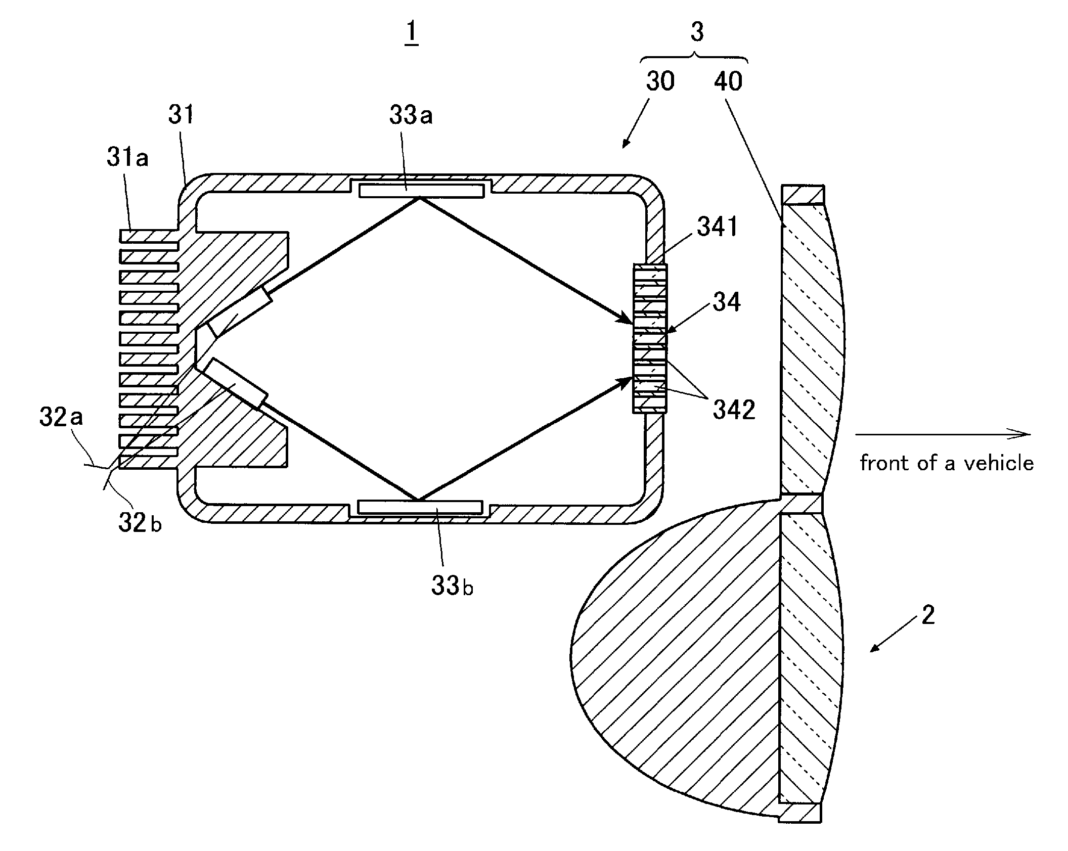
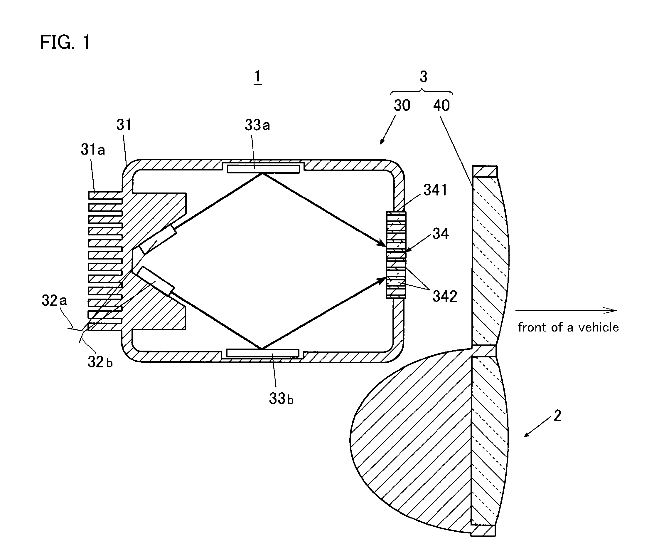
[0051]Exemplary embodiments of the disclosed subject matter will now be described in detail with reference to FIGS. 1 to 8. FIG. 1 is a schematic side cross-section view showing an exemplary embodiment of a vehicle headlight made in accordance with principles of the disclosed subject matter. The vehicle headlight 1 can include a common light distribution unit 2 and a variable light distribution unit 3.

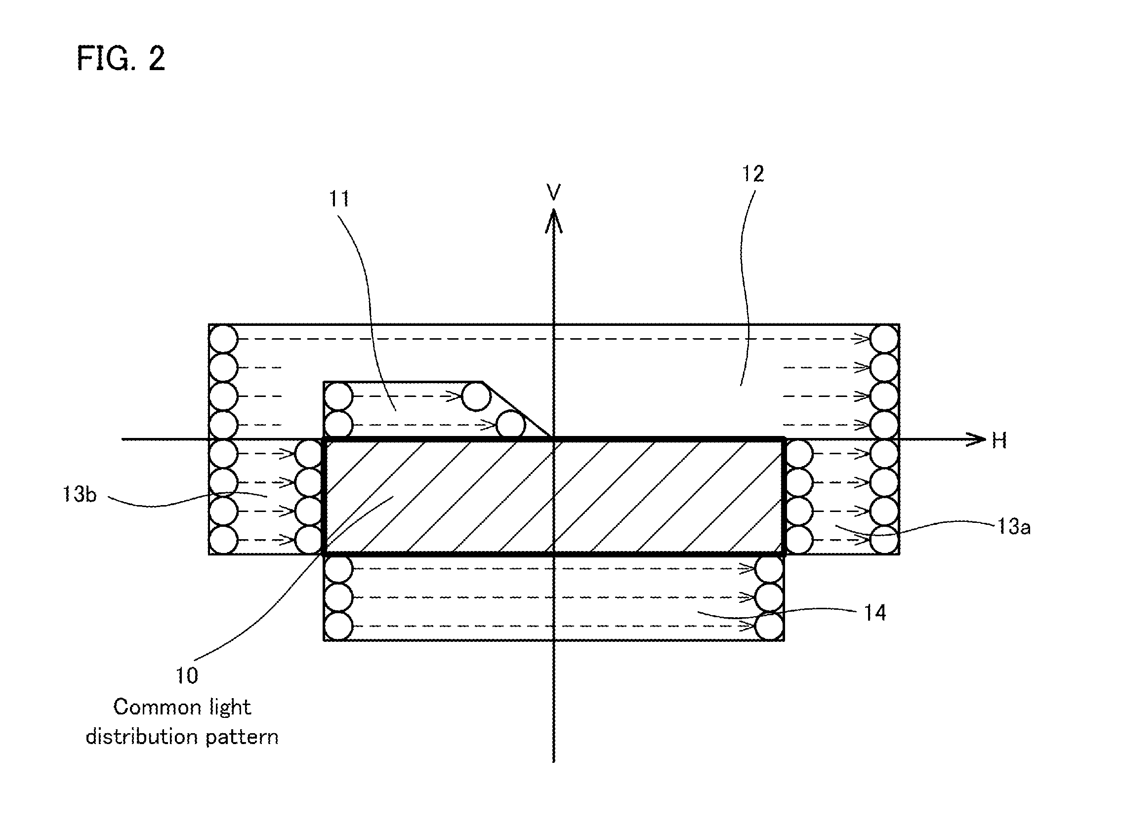
[0052]FIG. 2 is an explanatory diagram depicting an exemplary light distribution pattern formed by the vehicle headlight 1. The common light distribution unit 2 can form a common light distribution pattern 10 located under a horizontal line H, which is a common part of various light distribution patterns formed by the vehicle headlight 1. Accordingly, the common light distribution unit 2 can be structured by a common projector type headlight, a common reflector type headlight and the like.

[0053]The variable light distribution unit 3 can form various light distribution patterns, for exa...


PUM


Abstract

A vehicle headlight including a common light distribution unit and a variable light distribution unit and a headlight system including the headlight can form a common light distribution pattern and a variable light distribution pattern using the common and the variable light distribution units. The variable distribution unit can include a light source, a phosphor panel, a mirror reflecting/scanning light emitted from the light source onto the phosphor panel and a projector lens projecting the scanning light adjacent the common light distribution pattern. The headlight system can include a front sensor detecting a surrounding condition, and can control the common and the variable light distribution units to form an optimum light distribution pattern in accordance with surrounding conditions. Thus, the disclosed subject matter can provide a headlight system including a headlight that can form an optimum light distribution pattern in accordance with surrounding conditions and can have a simple structure.

Description

[0001]This application claims the priority benefit under 35 U.S.C. §119 of Japanese Patent Application No. 2010-089082 filed on Apr. 8, 2010, which is hereby incorporated in its entirety by reference.BACKGROUND[0002]1. Field[0003]The presently disclosed subject matter relates to a vehicle headlight and a headlight system using the same, and more particularly to a vehicle headlight using a semiconductor light source and a minor that can provide various light distribution patterns while having a simple structure and the headlight system using the same that can vary a light distribution pattern in accordance with surroundings such as an oncoming vehicle, a forward travelling vehicle, a road, etc.[0004]2. Description of the Related Art[0005]Vehicle headlights that can vary a light distribution pattern to maintain a high visibility in accordance with surroundings such as an existence of an oncoming vehicle, a forward travelling vehicle and the like have been developed in recent years. A ...

Claims


Application Information

Patent Timeline
Patent Type & Authority Applications(United States)
IPC IPC(8): F21V9/00F21V7/00B60Q1/04
CPCB60Q1/085B60Q2300/41F21Y2101/025B60Q2300/45B60Q2300/42F21Y2115/10F21Y2115/30F21S41/141F21S41/16F21S41/176F21S41/125F21S41/13F21S41/25F21S41/675F21V9/30
Inventor KUSHIMOTO, TAKUYA
Owner STANLEY ELECTRIC CO LTD
Why Eureka
Try Eureka