Light emitting device and illumination apparatus including same

a technology of light emitting devices and illumination apparatuses, applied in lighting and heating apparatuses, lighting support devices, instruments, etc., can solve the problems of surface reflection and granule-like distribution of lights, and achieve the effect of preventing non-uniform light distribution and low directivity

Active Publication Date: 2012-11-01
PANASONIC CORP
View PDF7 Cites 35 Cited by
  • Summary
  • Abstract
  • Description
  • Claims
  • Application Information

AI Technical Summary

Benefits of technology

[0026]In accordance with the aspects of the present invention, since most of lights emitted from the solid-state light emitting devices into the accommodating portion of the light distribution adjusting member are totally reflected by the concave curved surface portion to propagate in the lateral dir...

Problems solved by technology

This results in a non-uniform distribution of luminance at the output surface (the diffusion and transmission panel 107) of the ill...

Method used


Image

  • Light emitting device and illumination apparatus including same
  • Light emitting device and illumination apparatus including same
  • Light emitting device and illumination apparatus including same

Examples


first embodiment

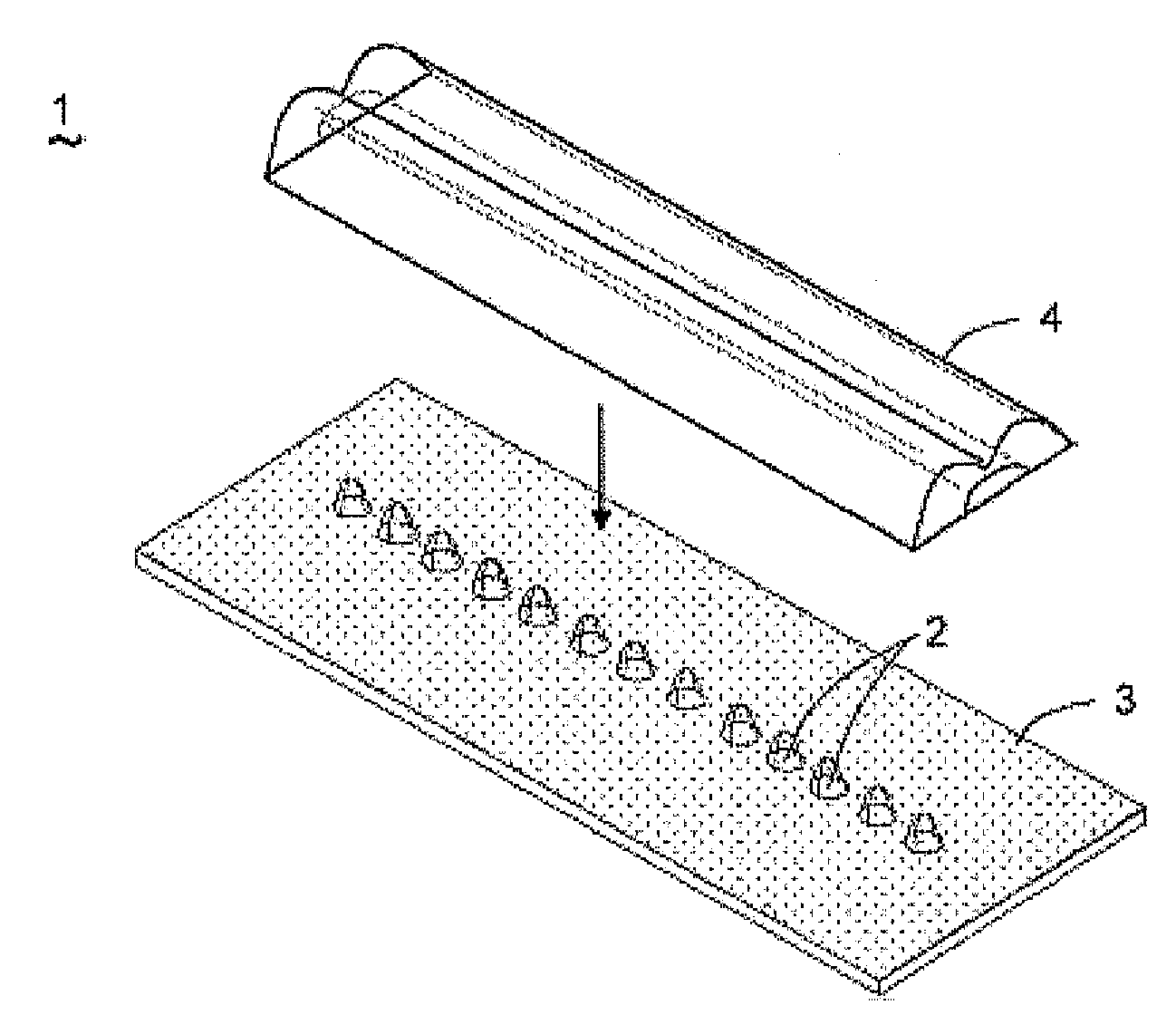
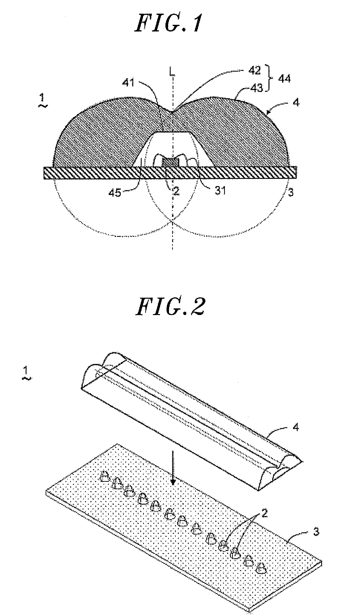
[0048]Hereinafter, a light emitting device and an illumination apparatus including same in accordance with the present invention will be described with reference to FIGS. 1 to 4C. In this embodiment, as shown in FIGS. 1 and 2, a light emitting device 1 includes a plurality of light emitting diodes (LEDs) 2 as solid-state light emitting elements; a wiring board (hereinafter abbreviated as a “board”) 3 on which the LEDs 2 are arranged in the form of an array; and a light distribution adjusting member 4 which adjusts a distribution of lights emitted from the LEDs 2.

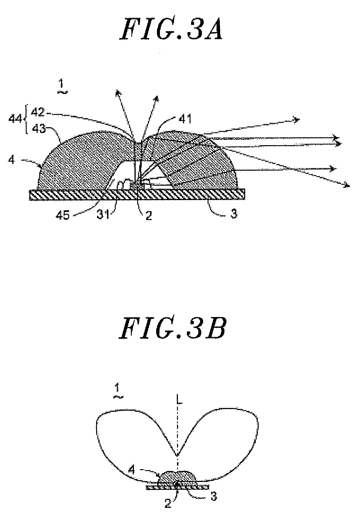
[0049]The light distribution adjusting member 4 is provided to commonly cover at least two of the LEDs 2. The light distribution adjusting member 4 includes an accommodating portion 41 which accommodates the LEDs 2; a concave curved surface portion 42 provided above light output surfaces of the LEDs and immediately above the LEDs 2; and a pair of convex curved surface portions 43 provided in opposite sides of the concave cur...

second embodiment

[0079]Next, a light emitting device in accordance with the present invention will be described with reference to FIGS. 6 and 7. In this embodiment, the light emitting device 1 further includes a diffusion and transmission cover member (hereinafter abbreviated as a “diffusion cover”) 71 covering the light distribution adjusting member 4, as shown in FIG. 6. In this embodiment, the light output surface of the LED 2 is also covered with the hemispherical wavelength converting member 92, as shown in FIG. 7.

[0080]The diffusion cover 71 is a tubular optical member provided with an accommodating space in which the light distribution adjusting member 4 can be accommodated, the optical member having an open side opposite to the board 3, and is made of a milky white material obtained by adding a white paint to a transparent resin such as an acryl resin or the like. In addition, as shown in FIG. 7, in a cross section of the diffusion cover 71 in the width direction, two opposite side portions ...

third embodiment

[0082]Next, a light emitting device and an illumination apparatus including same in accordance with the present invention will be described with reference to FIGS. 8A and 8B. In this embodiment, as shown in FIG. 8A, a light emitting device 1 is configured such that the light output surface 44 of the light distribution adjusting member 4 is a rough surface. In FIGS. 8A and 8B, the rough surface is indicated by a thick line. A roughening process of the light output surface 44 is performed with a roughness of, e.g., #100 by sand blast. In the roughness, an area ratio of fine concave portions (not shown) to smooth portions (not shown) is, for example, 1:1 without being limited thereto but may be properly adjusted by controlling a distribution of lights emitted from the light distribution adjusting member 4. This is true of a grain diameter of the sand blast.

[0083]However, if the light output surface 44 is a smooth surface, lights (direct lights) refracted and propagated through the ligh...


PUM

PropertyMeasurementUnit
Thicknessaaaaaaaaaa
Angleaaaaaaaaaa
Transparencyaaaaaaaaaa

Abstract

A light emitting device includes a plurality of solid-state light emitting elements; a board on which the solid-state light emitting elements are arranged in the form of an array; and a light distribution adjusting member for adjusting a distribution of lights outputted from the solid-state light emitting elements. The light distribution adjusting member is provided to commonly cover at least two of the solid-state light emitting elements, and includes an accommodating portion which accommodates the solid-state light emitting elements; a concave curved surface portion provided above light output surfaces of the solid-state light emitting elements and immediately above the solid-state light emitting elements; and a pair of convex curved surface portions which are provided in opposite sides of the concave curved surface portion, each of the convex curved surface portions being smoothly connected to the concave curved surface portion.

Description

FIELD OF THE INVENTION[0001]The present invention relates to a light emitting device including a plurality of solid-state light emitting elements as a light source, and an illumination apparatus including the light emitting device.BACKGROUND OF THE INVENTION[0002]Because of their low power consumption, high luminance and high durability, light emitting diodes (LEDs) are in the spotlight as a light source for an illumination apparatus with which incandescent lamps, fluorescent lamps and the like are replaced. However, since a single LED provides less light intensity than a fluorescent lamp, a light emitting device including a plurality of LEDs is used for a general illumination apparatus having LEDs as a light source.[0003]As one example of such a type of light emitting device, as shown in FIG. 19A, there has been known a light emitting device 101 in which a plurality of LEDs 102 is mounted on an elongated board 103 in a line and a semicylindrial transparent resin part 104 is provide...

Claims


Application Information

Patent Timeline
IPC IPC(8): F21V5/04F21V9/08F21V21/00F21V21/005
CPCF21V3/0445F21V3/0481H01L2924/01047H01L2224/45144H01L2224/45124H01L2224/48091F21Y2103/022F21Y2101/02H01L2224/45147F21Y2103/003F21V13/12F21V5/007F21V5/043F21V9/08F21V13/02H01L2924/00014H01L2924/00G02B19/0066F21V5/04F21V7/0091G02B19/0028H01L2224/45139F21Y2103/10F21Y2115/10F21Y2103/33F21V3/12F21V3/0625
Inventor YOKOTANI, RYOJIKIBA, KEIJI
Owner PANASONIC CORP
Why Eureka
Try Eureka