Device with dynamic magnet loudspeaker

a dynamic magnet and loudspeaker technology, applied in the direction of deaf-aid sets, electrical transducers, transducer details, etc., can solve the problems of disadvantageous holes in the moisture-proof and overall tightness of these products, and achieve the effects of low directivity, reduced spatial volume and overall weight, and loud and clear sound

Active Publication Date: 2011-10-06
THE WEATHER CHANNEL
View PDF39 Cites 15 Cited by
  • Summary
  • Abstract
  • Description
  • Claims
  • Application Information

AI Technical Summary

Benefits of technology

[0007]In view of the aforesaid shortcomings of the prior art, the inventor of the present invention put years of practical experience into research and experiment and finally succeeded in developing a device with a dynamic magnet loudspeaker and thus overcoming the bottleneck of existing loudspeaker manufacturing technology. The device with the dynamic magnet loudspeaker disclosed herein not only has a significantly reduced spatial volume and overall weight, but also can generate a loud and clear sound with low directivity.
[0009]In the device with the dynamic magnet loudspeaker of the present invention, the housing member itself can transmit sound outward, so there is no need to drill holes in the peripheral surfaces of the housing member. By contrast, commercially available laptop computers, cell phones, PDAs, portable audio players, etc. must be provided with holes to enable sound propagation from loudspeakers, and the holes are disadvantageous to moisture-proof and overall tightness of these products. However, when the device of the present invention is used in the foregoing products, moisture-proof and overall tightness of the products can be substantially increased, for the peripheral surfaces of the housing member need not be drilled.

Problems solved by technology

By contrast, commercially available laptop computers, cell phones, PDAs, portable audio players, etc. must be provided with holes to enable sound propagation from loudspeakers, and the holes are disadvantageous to moisture-proof and overall tightness of these products.

Method used


Image

  • Device with dynamic magnet loudspeaker
  • Device with dynamic magnet loudspeaker
  • Device with dynamic magnet loudspeaker

Examples


Embodiment Construction

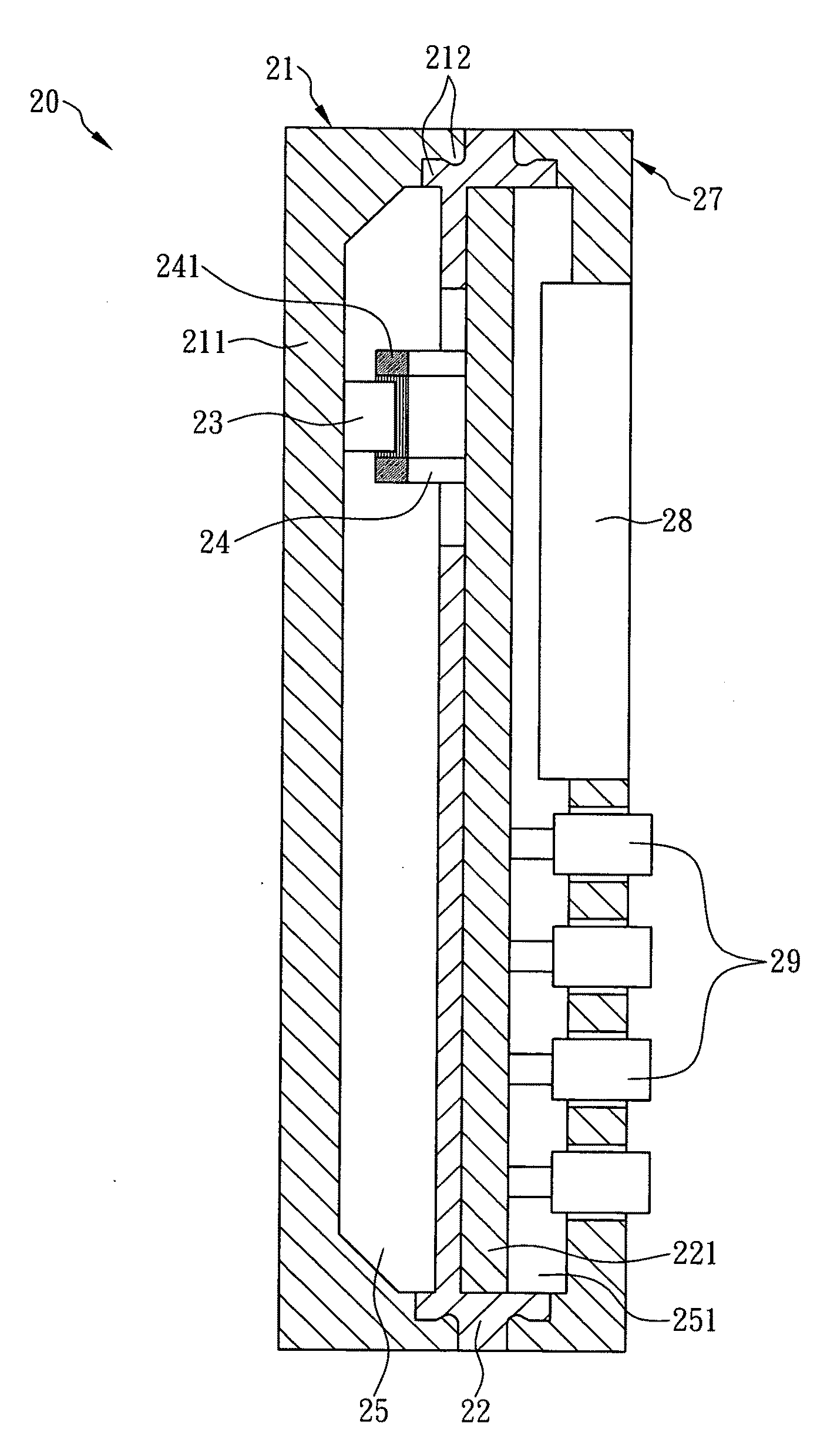
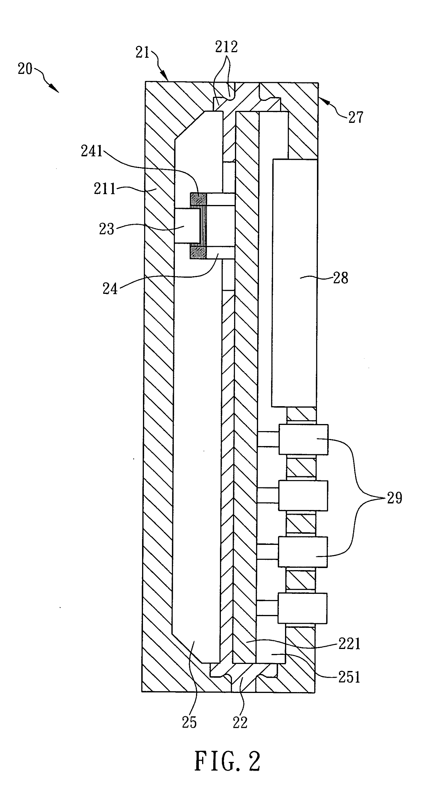
[0023]The present invention is directed to a device with a dynamic magnet loudspeaker. Referring to FIG. 2, a device 20 according to a first preferred embodiment of the present invention is a handheld electronic device (e.g., a laptop computer, a cell phone, a PDA, a portable audio player, a voice navigation device, a handheld game console, etc.). The device 20 includes a first housing member 21, a seat 22, a first magnetic element 23, a hollow tube 24, and a second housing member 27. In the present embodiment, the first housing member 21 has a square U-shaped cross-section. Moreover, the first housing member 21 has two ends each provided with a fastening element 212, and the seat 22 also has two ends each provided with a fastening element 212, wherein the fastening elements 212 of the first housing member 21 correspond in position to and can be fastened with the fastening elements 212 of the seat 22. When the corresponding fastening elements 212 of the first housing member 21 and o...


PUM


Abstract

The present invention is to provide a device with dynamic magnet speaker, which comprises a first housing member having a wall and a first magnetic element fixed on an inner surface of the wall; a seat having a first side connected to the first housing member to define a first receiving space between the first housing member and the first side of the seat; and a hollow tube fixedly provided on the seat and corresponding in position to the first magnetic element, wherein a first coil unit is fixedly mounted around the hollow tube, and the hollow tube extends toward the first magnetic element and is either mounted around an outer periphery of the first magnetic element or inserted in a first central hole of the first magnetic element, so as to not only reduce the weight and spatial volume thereof, but also substantially lower the directivity of sound produced.

Description

FIELD OF THE INVENTION[0001]The present invention relates to a device with loudspeaker, more particularly to a device with dynamic magnet speaker, which comprises a first housing member having a wall and a first magnetic element fixed on an inner surface of the wall; a seat having a first side connected to the first housing member to define a first receiving space between the first housing member and the first side of the seat; and a hollow tube fixed on the seat and corresponding in position to the first magnetic element, wherein a first coil unit is fixed around the hollow tube, and the hollow tube extends toward the first magnetic element and is either mounted around an outer periphery of the first magnetic element or inserted in a first central hole of the first magnetic element. Thus, when a current flows through and thereby magnetizes the coil unit, the magnetic lines generated by the coil unit and the magnetic lines generated by the magnetic element cause attraction or repuls...

Claims


Application Information

Patent Timeline
Patent Type & Authority Applications(United States)
IPC IPC(8): H04R1/00
CPCH04R1/28
Inventor WANG, CHAO-LANG
Owner THE WEATHER CHANNEL
Why Eureka
Try Eureka