Vehicle rearview mirror including a light-emitting diode apparatus

a technology of light-emitting diodes and rearview mirrors, which is applied in the field ofluminescent indicators, can solve the problems of increasing power consumption, not easy for a driver of an oncoming car or a pedestrian to achieve, and the total power consumption of using multiple devices at the same time will not be negligible, so as to achieve good light distribution, reduce power consumption, and widen the range

Inactive Publication Date: 2008-02-26
TOYODA GOSEI CO LTD
View PDF19 Cites 34 Cited by
  • Summary
  • Abstract
  • Description
  • Claims
  • Application Information

AI Technical Summary

Benefits of technology

[0022]It is an object of the invention to provide a luminescent indicator and a vehicle rearview mirror apparatus that allow a good light distribution in a wider range while offering reduced power consumption, long operating life and low-profiled body.

Problems solved by technology

Therefore, although power consumption in a device itself is reduced, the total power consumption in using multiple devices simultaneously will be not negligible.
Especially in lighting devices such as lamps, an increase in power consumption is significant.
Although the rearview mirror apparatus is attached projecting from the car width, it is not easy for a driver of oncoming car or a pedestrian to notice it in the night since it is relatively small.
Therefore, a driver of oncoming car, pedestrian or bicycle rider may have a minor collision with the rearview mirror apparatus.
Especially, a black rearview mirror apparatus must produce a worse visibility even when the body color is white or so.
However, the rearview mirror apparatus of prior art 1 has problems as described below.
(i) Since many bulbs are needed to illuminate the front face and side face of housing body, the power consumption must be increased to cause an increase in battery load.
(ii) Since the bulbs are attached to the support board through sockets, its depth is difficult to reduce.
Thus, it is not easy for the rearview mirror apparatus to be low-profiled.
However, even when LED's as many as bulbs are provided, there occurs unevenness in light intensity in the entire lighting range of rearview mirror light since LED has a light intensity lower than bulb.
Instead, when the number of LED's is increased to prevent the unevenness, the reduction effect of power consumption by using LED must be spoiled.
However, the linear light source unit of prior art 2 has the following problem.
Since light is entered from the intermediate interface through the hole into a plastic material again, there occurs unevenness in light distribution since the external radiation property of light lowers when a factor, e.g. stain, to block the transmission of light exists in the hole.

Method used


Image

  • Vehicle rearview mirror including a light-emitting diode apparatus
  • Vehicle rearview mirror including a light-emitting diode apparatus
  • Vehicle rearview mirror including a light-emitting diode apparatus

Examples


first embodiment

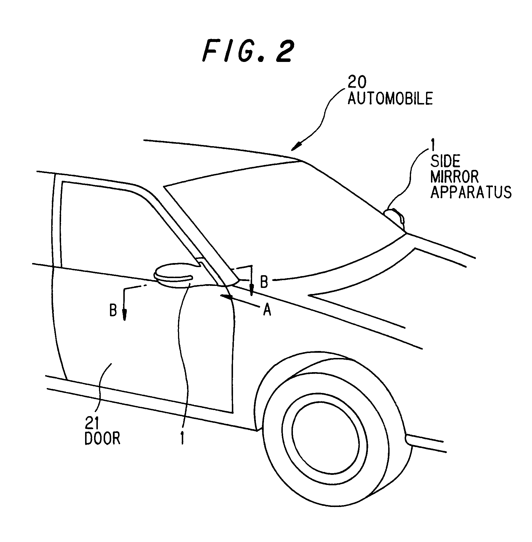
[0070]FIG. 2 shows a rearview mirror apparatus 1 in the first preferred embodiment of the invention.

[0071]The rearview mirror apparatus 1 is attached onto a front door 21 of automobile 20.

[0072]FIG. 3 is a front view showing the rearview mirror apparatus 1 being viewed in a direction A arrowed in FIG. 2.

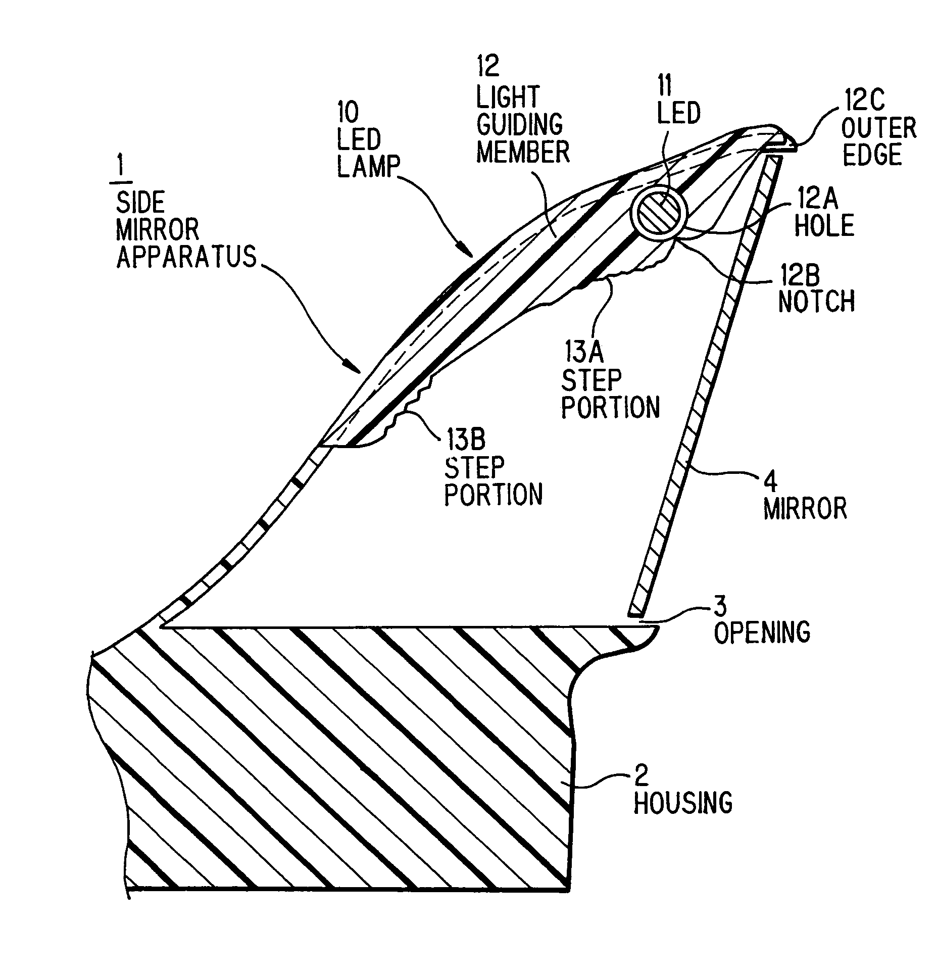
[0073]The rearview mirror apparatus 1 is composed of a housing 2 having a hollow structure made by resin molding, and an LED lamp 10 is disposed on the front-edge side thereof. The LED lamp 10 is designed such that it is integrated with the housing 2.

[0074]FIG. 4 is a cross sectional view cut along the line B-B in FIG. 3 to show the LED lamp 10 in FIG. 3.

[0075]An opening 3 is formed on the back side of the housing 2, and a mirror 4 is disposed to close the opening 3. The mirror 4 is rotatably fixed to a support member (not shown), for example, a support member with a rotation mechanism as shown in FIG. 1 or a support member with a motor-driven mechanism to be operated by a remote con...

second embodiment

[0101]FIG. 9 is a perspective view showing the rear section of an automobile 20. The rear section of automobile 20 is composed of: a hatch door 23 that is enabled to open and shut with a rear window 22; a bumper 24 that is of resin mold and is enabled to protect the rear portion of automobile 20; a rear combination lamp 25 that is provided at the rear corner of automobile 20; rear turn lamp 250 that has LED as a light source and is built in the rear combination lamp 25; a rear spoiler 30 that is of resin and is provided on the upper side of rear window 22; and a high-mount stop lamp 31 that is incorporated in the rear spoiler 30 and is enabled to radiate red light.

[0102]FIG. 10A is a cross sectional view cut along the line D-D in FIG. 9 to show the high-mount stop lamp 31 in the second preferred embodiment of the invention.

[0103]FIG. 10B is a top view showing a light-guiding member 12 of the high-mount stop lamp 31.

[0104]FIG. 10C is a partial front view showing a light radiation sur...

third embodiment

[0113]FIG. 11 is a cross sectional view cut along the line E-E in FIG. 9 to show the rear turn lamp 250 in the third preferred embodiment of the invention.

[0114]The rear turn lamp 250 is composed of a light-guiding member 12 that houses three plane radiation type LED's 11A, 11B and 11C in holes 12A and that is disposed inside an outer lens 251 of acrylic resin. The LED's 11A, 11B and 11C emit amber series light. Step portions 13A, 13B and 13C formed on a light reflection surface 120 are optically designed such that light from the LED's 11A, 11B and 11C is radiated in such a direction as not to disturb the driver of oncoming car. The number of LED's is not limited to three and may be one.

[0115]In the third embodiment, adding to the effects of the second embodiment, the car interior space can be increased since the protrusion volume of rear turn lamp 250 into the car interior can be reduced. Further, since the surface area of rear turn lamp 250 can be reduced, a design freedom of car ...


PUM


Abstract

A vehicle rearview mirror including a housing, a mirror, an LED that has a light emitting element and plane-radiates light in a direction nearly vertical to the optical axis of the light emitting element, and a light-guiding member in which at least the one LED is incorporated at a predetermined position. The light-guiding member has a light reflection surface that reflects light to be plane-radiated from the LED and that allows the reflected light to be radiated in a desired direction, and a light radiation surface that allows direct light to be directly emitted from the LED and the reflected light to be externally radiated by the light radiation surface.

Description

[0001]The present application is based on Japanese patent application Nos.2003-096752, 2003-096757 and 2004-73865, the entire contents of which are incorporated herein by reference.BACKGROUND OF THE INVENTION[0002]1. Field of the Invention[0003]The invention relates to a luminescent indicator with LED used as a light source and a vehicle rearview mirror apparatus and, particularly, to a luminescent indicator and a vehicle rearview mirror apparatus that allow an improved visibility while offering reduced power consumption, long operating life and low-profiled body.[0004]2. Description of the Related Art[0005]In recent years, LED's (light emitting diodes) are applied to various apparatuses because they have a long operating life and reduced power consumption as compared to conventional bulbs. Since a luminescent indicator using LED has a small light-source size, it is frequently used as a light source for a unit that is subject to a limitation on its dimension.[0006]On the other hand,...

Claims


Application Information

Patent Timeline
Patent Type & Authority Patents(United States)
IPC IPC(8): B60Q1/32F21V7/04B60Q1/00B60Q1/26B60Q1/30B60Q1/56B60R1/12F21K99/00F21S8/10F21V8/00
CPCB60Q1/26B60Q1/2665B60Q1/2669B60Q1/268B60Q1/302B60Q1/323B60Q1/56B60R1/1207F21S48/215F21S48/2237F21S48/2243F21S48/2262F21S48/2268F21S48/2281F21S48/2287G02B6/0038G02B6/0048B60Q1/2611F21Y2101/02F21W2111/027F21W2111/08H01L2924/181H01L2224/48091H01L2224/48247H01L2924/1815F21Y2115/10F21S43/14F21S43/237F21S43/239F21S43/243F21S43/245F21S43/249F21S43/247H01L2924/00012H01L2924/00014
Inventor TANAKA, YOSHIHARUMISAWA, AKIHIROTAKAHASHI, TOSHINORI
Owner TOYODA GOSEI CO LTD
Why Eureka
Try Eureka