Vehicle headlight

a headlight and vehicle technology, applied in the field of vehicle headlights, can solve the problems of difficult to employ as a headlight for a single passenger vehicle, harassment of pedestrians and oncoming vehicles, and may risk the safety of drivers, and achieve the effects of simple structure, favorable fail-safe structure, and enhanced visibility for driving

Active Publication Date: 2014-01-02
STANLEY ELECTRIC CO LTD
View PDF10 Cites 34 Cited by
  • Summary
  • Abstract
  • Description
  • Claims
  • Application Information

AI Technical Summary

Benefits of technology

[0018]The disclosed subject matter has been devised to consider the above and other problems, features, and characteristics. Thus, embodiments of the disclosed subject matter can include a vehicle headlight unit using a light source unit and a movable mirror that can provide various light distribution patterns with a compact structure such that can be employed as a headlight for a small size car. The disclosed subject matter can also include a vehicle headlight that can form various light distribution patterns to enhance visibility for driving, with a simple structure, and which can include a favorable fail safe structure even when an actuator thereof fails to operate properly due to various causes, such as a disconnection, mechanical fatigue, and the like.

Problems solved by technology

The conventional vehicle headlight 200 using such a structure may be subject to a large-scaled headlight, and therefore may be difficult to employ as a headlight for a small size car such as a single passenger vehicle, etc.
In this case, the conventional vehicle headlight 200 may emit the visual light intensively in a constant direction by the movable mirror 209, which stays at the default position, and therefore may not only cause harassments for pedestrians and oncoming vehicles but also may risk to a driver safety.
However, light source devices disclosed in these conventional devices may also cause problems similar to these of the conventional headlight 200 as described above.

Method used


Image

  • Vehicle headlight
  • Vehicle headlight
  • Vehicle headlight

Examples


Embodiment Construction

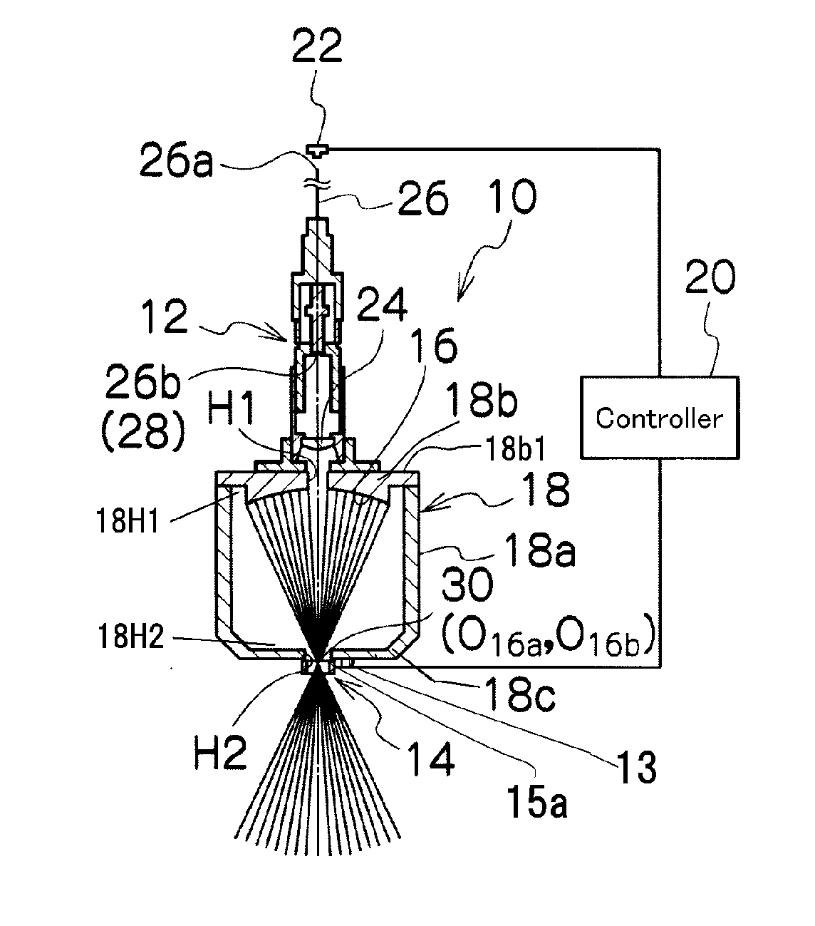
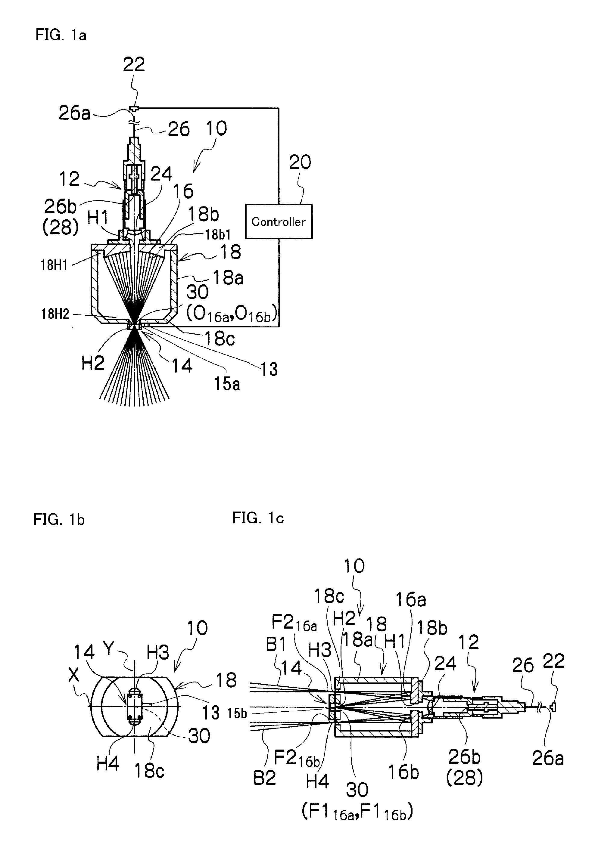
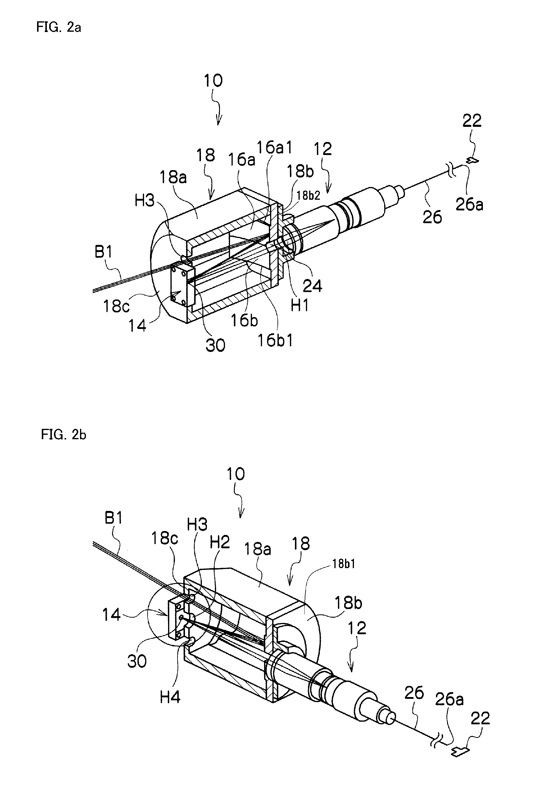
[0033]Exemplary embodiments of the disclosed subject matter will now be described in detail with reference to FIG. 1a to FIG. 4c. FIGS. 1a, 1b and 1c are a schematic top cross-sectional view, a front view and a side cross-sectional view showing an exemplary embodiment of a vehicle headlight made in accordance with principles of the disclosed subject matter, respectively. The vehicle headlight 10 can be attached to a front right or a front left of a vehicle. When the vehicle is a small car such as a single passenger vehicle, the vehicle headlight may be attached to a front middle of the vehicle.

[0034]The vehicle headlight 10 can include: a housing 18 including a body 18a, which is formed in a tubular shape having a first opening 18H1 and a second opening 18H2, a first end plate 18b having a third opening H1 being located adjacent the first opening 18H1 of the body 18a, and a second end plate 18c having a fourth opening H2, a fifth opening H3 and a sixth opening H4, and located adjace...


PUM


Abstract

A vehicle headlight can form a variable light distribution pattern with a simple structure including a favorable fail-safe. The headlight can include a movable mirror facing a light source unit, a static mirror between the movable mirror and the light source unit and a controller to emit light from the light source unit and to scan the light toward the static mirror using the movable mirror having a default position, where receives the light at a position substantially perpendicular thereto. The controller can enable the headlight to provide various light distribution patterns by varying a scanning method and the movable mirror is configured to return the light toward the light source unit even if it fails to operate properly. Thus, the disclosed subject matter can provide a vehicle headlight that can form various light distribution patterns in accordance with surroundings and can have the simple structure including the favorable fail-safe.

Description

[0001]This application claims the priority benefit under 35 U.S.C. §119 of Japanese Patent Application No. 2012-144195 filed on Jun. 27, 2012, which is hereby incorporated in its entirety by reference.BACKGROUND[0002]1. Field[0003]The presently disclosed subject matter relates to a vehicle headlight, and more particularly to a small vehicle headlight using a semiconductor light source and a movable mirror, which can provide various light distribution patterns from at least one small light-emitting opening for a low beam, a high beam and the like, and which can vary a favorable light distribution pattern in accordance with surroundings such as an oncoming vehicle, a forward travelling vehicle, a road, etc.[0004]2. Description of the Related Art[0005]Vehicle headlights using a semiconductor light source and a movable mirror, which can vary a light distribution pattern to maintain a high visibility in accordance with surroundings such as an existence of an oncoming vehicle, a forward t...

Claims


Application Information

Patent Timeline
Patent Type & Authority Applications(United States)
IPC IPC(8): B60Q1/08F21S8/10
CPCB60Q1/08F21S48/1757F21S48/1208B60Q1/085B60Q2300/056B60Q2300/42B60Q2300/45F21S41/16F21S41/176F21S41/321F21S41/365F21S41/60F21S41/675F21S45/70
Inventor NAKAYA, KISHO
Owner STANLEY ELECTRIC CO LTD
Why Eureka
Try Eureka