Display system for viewing multiple video signals

a display system and video signal technology, applied in the field of display systems for viewing multiple video signals, can solve the problems of small differences in the behaviour of the two displays, the disadvantage of placing two high-resolution displays on the work desk, and the extra space and cost of all of them, so as to achieve the highest efficiency or performance of the user, the effect of maximizing one or more image quality, user performance or user work throughput, and maximizing the effect of image quality

Inactive Publication Date: 2007-05-31
BARCO NV
View PDF4 Cites 221 Cited by
  • Summary
  • Abstract
  • Description
  • Claims
  • Application Information

AI Technical Summary

Benefits of technology

[0022] In embodiments of the present invention, the method may furthermore comprise adapting characteristics of individual zones of the active display area in order to improve, e.g. maximize, one or more of image quality, user efficiency, user performance or user work throughput. Highest efficiency or performance of the user means highest possible quality of work delivered by the user of the display or highest possible work throughput of the user of the display.
[0023] This adapting characteristics of individual zones of the active display area in order to improve, e.g. maximize, image quality or user efficiency or user performance or work throughput of the user may include one or more of changing peak luminance, changing colour point, changing colour profile or changing transfer curve of an individual zone of the active display area. This adapting characteristics of individual zones of the active display area in order to improve, e.g. maximize, image quality or user efficiency or user performance or work throughput of the user may include performing an individual calibration, and thus using different calibration data, for individual zones of the active display area. This way, different zones of the display, corresponding to different image signals to be displayed, can have different calibration tables, so that calibrated colour points or colour profiles for different images to be displayed in different zoned can be retained in a display according to embodiments of the present invention. Performing an individual calibration or using different calibration data for individual zones of the active display area may for example include calibration to DICOM GSDF or using calibration data to comply with DICOM GSDF. This is particularly useful f or medical images.

Problems solved by technology

However, there exist several problems with the above solution.
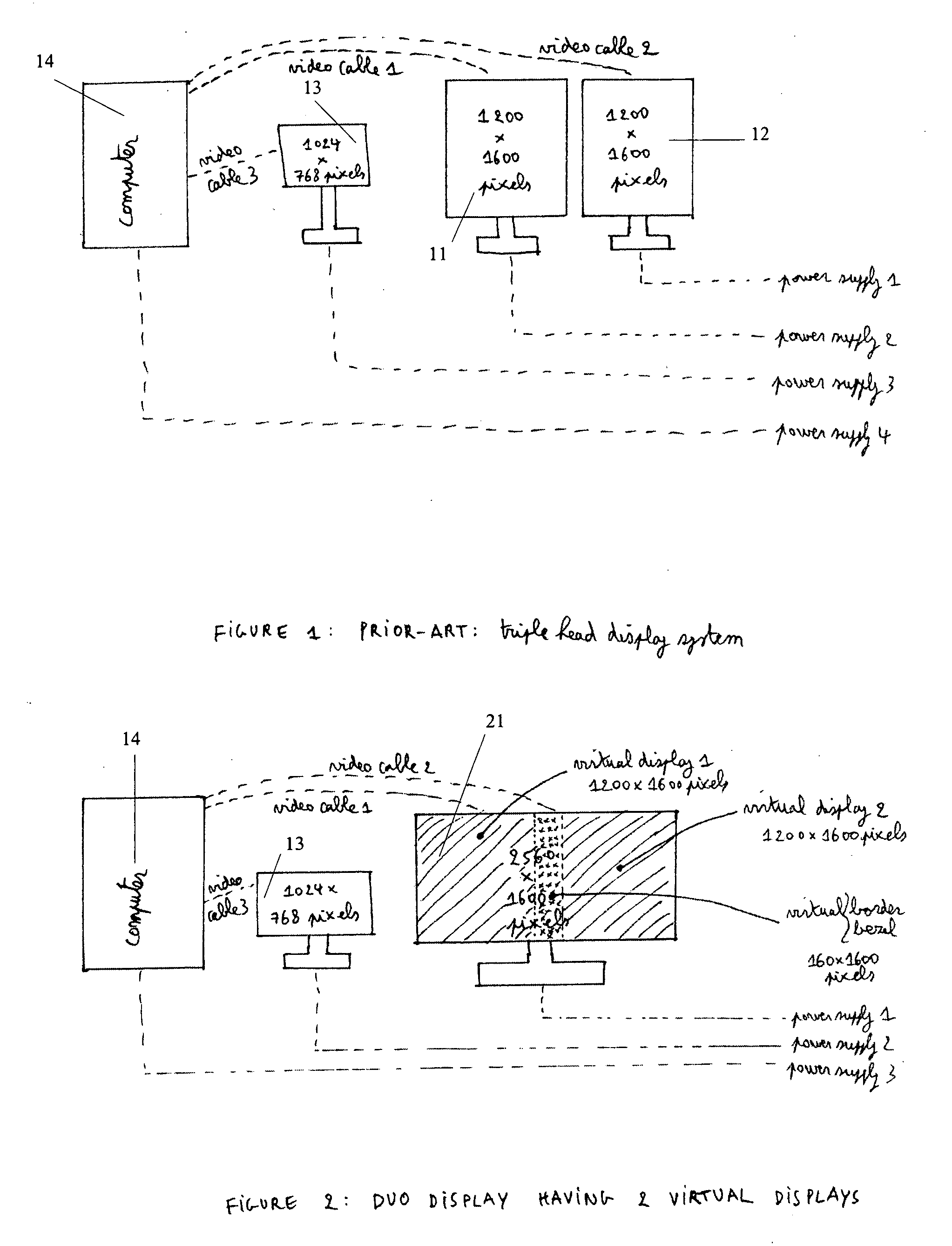
First of all, the fact that two high-resolution displays need to be placed on the work desk is not advantageous since too much place is lost.
. . This all takes extra space and is more expensive because of duplication of components (such as power supply, video cables, .
But the disadvantages are not limited to ergonomic aspects: there are also quality problems when using two separate displays for displaying video signals that are related to each other (such as but not limited to the prior and current exam).
When using two separate displays there will be problems such as (small) differences in behaviour of the two displays.
In such situations it is very difficult to make the two displays that are placed next to each other “look the same” or in other words make them have the same behaviour.
Another disadvantage of using two separate displays is that the images of the two displays are not shown completely next to each other.
In some situations this is a problem since it could lower the sensitivity of the radiologist to perceive subtle image features.

Method used


Image

  • Display system for viewing multiple video signals
  • Display system for viewing multiple video signals
  • Display system for viewing multiple video signals

Examples


Embodiment Construction

[0052] The present invention will be described with respect to particular embodiments and with reference to certain drawings but the invention is not limited thereto but only by the claims. The drawings described are only schematic and are non-limiting. In the drawings, the size of some of the elements may be exaggerated and not drawn on scale for illustrative purposes. Where the term “comprising” is used in the present description and claims, it does not exclude other elements or steps.

[0053] It should be appreciated that in the description of exemplary embodiments of the invention, various features of the invention are sometimes grouped together in a single embodiment, figure, or description thereof for the purpose of streamlining the disclosure and aiding in the understanding of one or more of the various inventive aspects. This method of disclosure, however, is not to be interpreted as reflecting an intention that the claimed invention requires more features than are expressly ...


PUM


Abstract

The present invention provides a method and device for displaying a plurality of video signals on one single display. According to embodiments of the present invention a plurality of display systems can be replaced by one display system being fully backwards compatible without the need to change any software or hardware components such as application software, graphical boards, . . . The present invention can also guarantee that even though a plurality of displays are being replaced by one single display still individual characteristics of those plurality of displays are being retained by the new display.

Description

CROSS-REFERENCE TO RELATED APPLICATION [0001] This application claims the benefit of provisional application Ser. No. 60 / 738,983 filed Nov. 23, 2005 under 35 U.S.C. 119(e), the disclosure of which is herein incorporated by reference.FIELD OF THE INVENTION [0002] The present invention relates to a system and method for simultaneous viewing of multiple video signals. The invention applies to display systems such as, amongst others, but not limited thereto, plasma display systems, field emission display systems, liquid crystal display systems, electroluminescent (EL) display systems, light emitting diode (LED) and organic light emitting diode (OLED) display systems, especially flat panel display systems used in projection or direct viewing concepts. The invention applies to both monochrome and colour display systems and to emissive, transmissive, reflective and trans-reflective display technologies. BACKGROUND OF THE INVENTION [0003] In medical imaging, radiologists typically make use ...

Claims


Application Information

Patent Timeline
Patent Type & Authority Applications(United States)
IPC IPC(8): G09G5/00
CPCG06F3/03547G06F3/14G09G5/006G09G5/14G09G2320/0693G06F19/321G16H30/20
Inventor DE PAEPE, LODEKIMPE, TOM
Owner BARCO NV
Why Eureka
Try Eureka