

Ceramic-glass composite electrode and fluorescent lamp having the same
a composite electrode and fluorescent lamp technology, applied in the manufacture of electrode assemblies, low-pressure discharge lamps, discharge tubes luminescnet screens, etc., can solve the problems of major problems of fluorescent lamps, shorten the lifetime of fluorescent lamps, increase manufacturing costs, etc., to prevent adhesives from flowing, reduce costs, and simple structure
- Summary
- Abstract
- Description
- Claims
- Application Information
AI Technical Summary
Benefits of technology
Problems solved by technology
Method used
Image

Examples
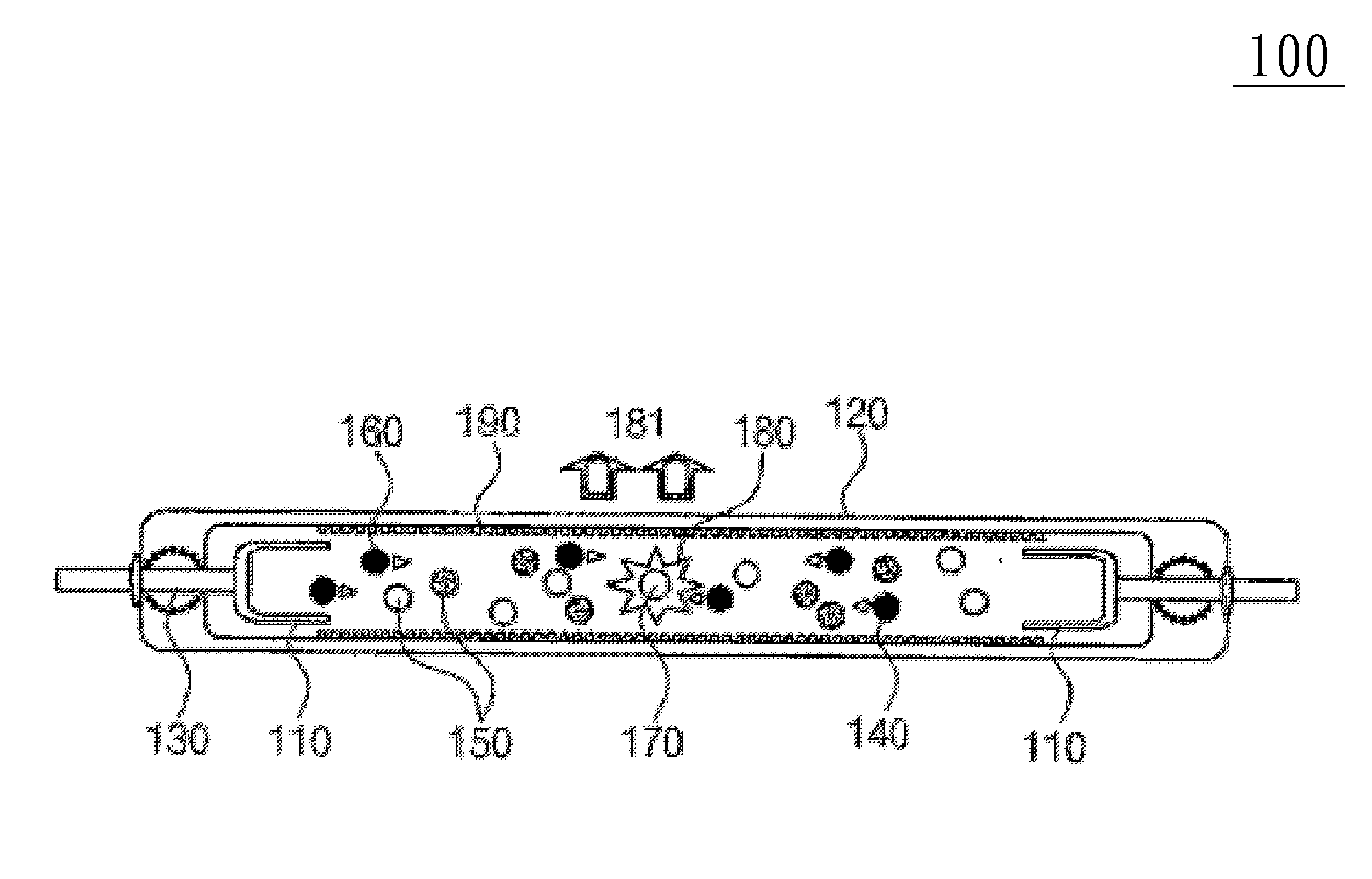
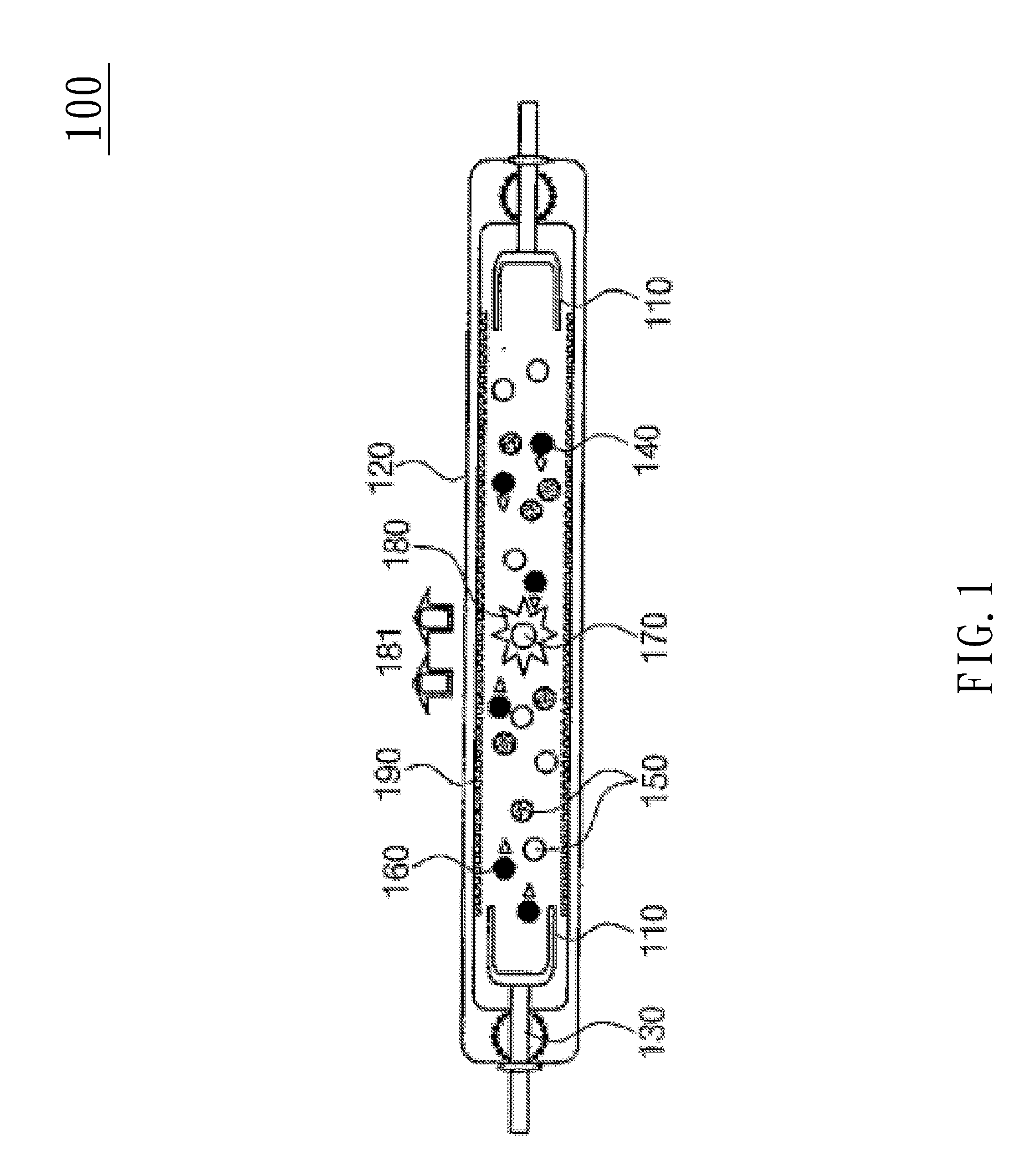
first embodiment
[0035]According to the present invention, the material of the electrodes 430, 460 includes the following compositions.
(CaO—MgO—SrO—ZrO2—TiO2)+Glass frits A Formula 1:
[0036]The proportions of the compositions in the material of Formula 1 (Samples EC1 to EC6) are shown in Table 1; their dielectric constants and losses are measured at room temperature. The results are shown in Table 1 as follows.
TABLE 1Compositions (mol)DielectricDielectricSampleCaOMgOSrOZrO2TiO2ConstantLoss (%)EC10.650.050.30.970.0332.30.19EC20.650.050.30.90.138.20.1EC30.650.050.30.80.251.10.12EC40.650.050.30.70.366.20.15EC50.650.050.30.60.484.80.12EC60.650.050.30.50.5105.10.25
[0037]The glass-frit additive adopted is the leadless glass SF-44 used in glass tubes. Because its heat expansion coefficient is 95×10−7 / K, the heat expansion coefficient can be adjusted by adding 0.6 mol of BaO and 0.4 mol of CaO to 1 mol of SiO2. Alternatively, add 0.3˜10 wt % of glass frits, which has identical compositions as leadless glas...
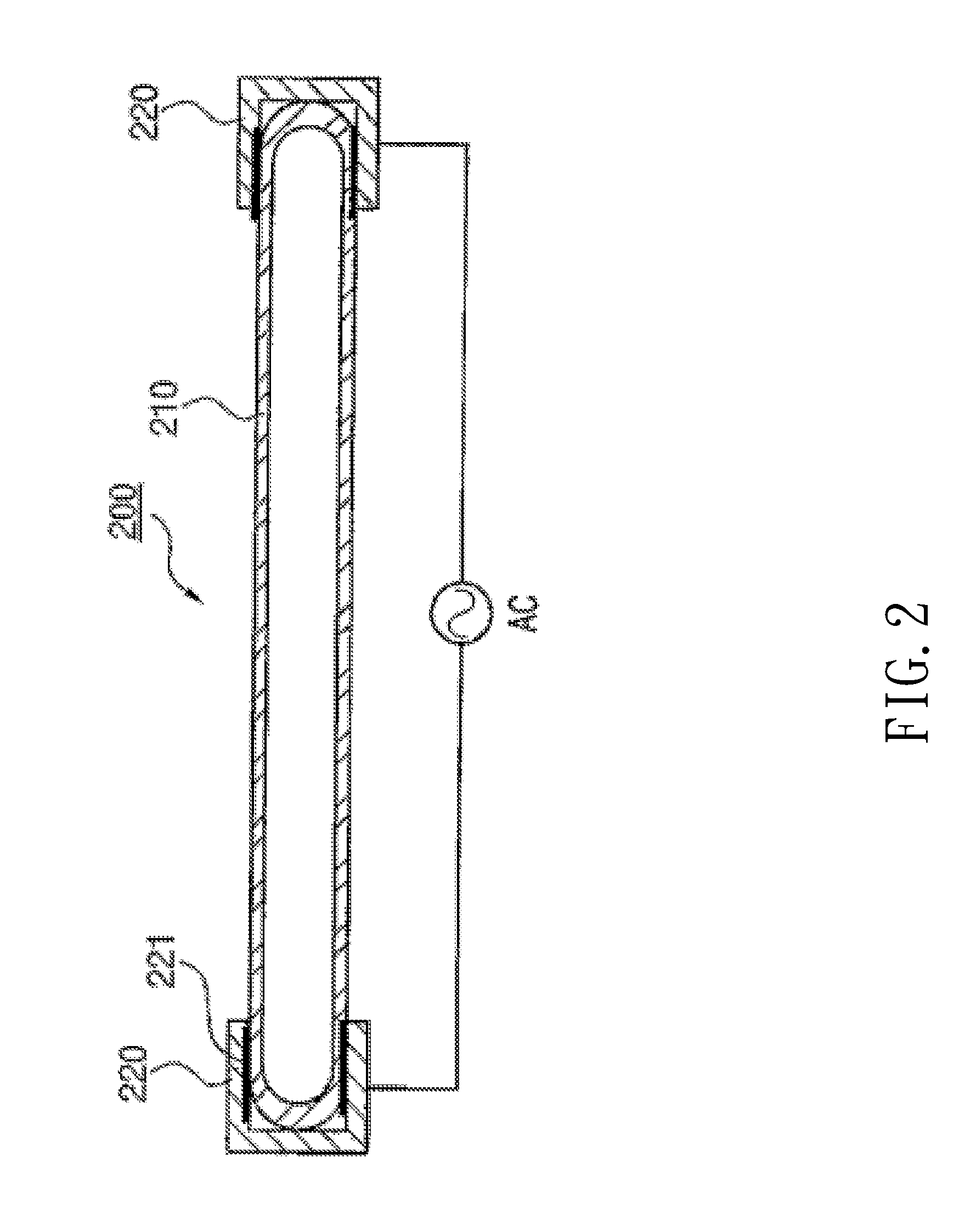
second embodiment
[0046]According to the present invention, the material of the ceramic-glass composite electrodes includes the following compositions.
(CaO—MgO—SrO—ZrO2—TiO2)+Glass frits B Formula 2:
[0047]The proportions of the compositions in the material of Formula 2 are shown in Table 5; their dielectric constants and losses are measured at room temperature. The results are shown in Table 5 as follows.
TABLE 5Compositions (mol)DielectricDielectricSampleCaOMgOSrOZrO2TiO2ConstantLoss (%)ECB10.650.050.30.970.0325.00.12ECB20.650.050.30.90.128.00.1ECB30.650.050.30.80.241.00.12ECB40.650.050.30.70.354.00.15ECB50.650.050.30.60.465.40.12ECB60.650.050.30.50.588.50.13
[0048]The glass-frit additive adopted is the borosilicate used in glass tubes. Because its heat expansion coefficient is 33×10−7 / K, the heat expansion coefficient can be adjusted by adding 75 wt % of SiO2, 18 wt % of B2O3, 4 wt % of Na2O, 2 wt % of K2O, and 1 wt % of Al2O3. Synthesize the glass frits at 1,100 ° C., and then add the synthesized ...
PUM
 Abstract
Description
Claims
Application Information