Method for detecting transverse mode vibrations in an ultrasonic hand piece/blade

a transverse mode and ultrasonic technology, applied in the field of ultrasonic surgical systems, can solve the problems of increasing the risk of spreading infectious diseases to the operating room personnel, relatively wide thermal tissue damage zones, and vibrations and heat uncontrolled or undamped

Inactive Publication Date: 2003-07-08
ETHICON ENDO SURGERY INC
View PDF28 Cites 938 Cited by
  • Summary
  • Abstract
  • Description
  • Claims
  • Application Information

AI Technical Summary

Benefits of technology

The method provides automatic detection of off-resonance transverse mode vibrations in an ultrasonic hand piece / blade. Moreover, the method permits the easy identification of bad hand pieces and / or blades. As a result, patient safety and recuperation time are increased due to the reduction of damage to tissue surrounding the narrow area of coagulation. In addition, the method, avoids the costs associated with adding an FFT analyzer to the software / hardware of the generator to perform frequency sweeps to detect transverse modes.

Problems solved by technology

However, such instruments employ very high temperatures to achieve coagulation, causing vaporization and fumes as well as splattering, which increases the risk of spreading infectious diseases to operating room personnel.
Additionally, the use of such instruments often results in relatively wide zones of thermal tissue damage.
One of the problems associated with such ultrasonic cutting instruments is uncontrolled or undamped vibrations and the heat, as well as material fatigue resulting therefrom.
However, this could result in insufficient power to the blade at a time when it is needed for the most effective treatment of the patient.
In response to a switch on the hand piece or a foot switch connected to the generator by another cable, the generator signal is applied to the transducer, which causes a longitudinal vibration of its elements.
This arrangement is inflexible since the power versus load characteristics of the output of such a system can not be optimized to various types of hand piece transducers and ultrasonic blades.
The performance of traditional analog ultrasonic power systems for surgical instruments is affected by the component tolerances and their variability in the generator electronics due to changes in operating temperature.
However, these traditional ultrasonic drive systems have little to no flexibility with regards to adaptive frequency control.
The prior art ultrasonic generator systems also have little flexibility with regard to amplitude control, which would allow the system to employ adaptive control algorithms and decision making.
For example, these fixed systems lack the ability to make heuristic decisions with regards to the output drive, e.g., current or frequency, based on the load on the blade and / or the current to voltage phase angle.
It also limits the system's ability to set optimal transducer drive signal levels for consistent efficient performance, which would increase the useful life of the transducer and ensure safe operating conditions for the blade.
Further, the lack of control over amplitude and frequency control reduces the system's ability to perform diagnostic tests on the transducer / blade system and to support troubleshooting in general.
Another problem associated with the prior art ultrasonic systems is unwanted vibrations in the hand piece / blade.
Excess transverse mode vibrations generate heat which can lead to high blade sheath temperatures.
Such excessive heat can also heat the blade and cause damage to tissue surrounding the narrow zone of coagulation, which can adversely affect patient healing and recovery time.
In addition, transverse mode vibrations can also cause blade tip failures.
The vibrations may also be indicative of defects in the hand piece, such as damaged transducer disks.
While excess transverse mode vibrations are often audible, too often a user will ignore them until the ultrasonic generator can no longer drive the hand piece / blade.

Method used


Image

  • Method for detecting transverse mode vibrations in an ultrasonic hand piece/blade
  • Method for detecting transverse mode vibrations in an ultrasonic hand piece/blade
  • Method for detecting transverse mode vibrations in an ultrasonic hand piece/blade

Examples


Embodiment Construction

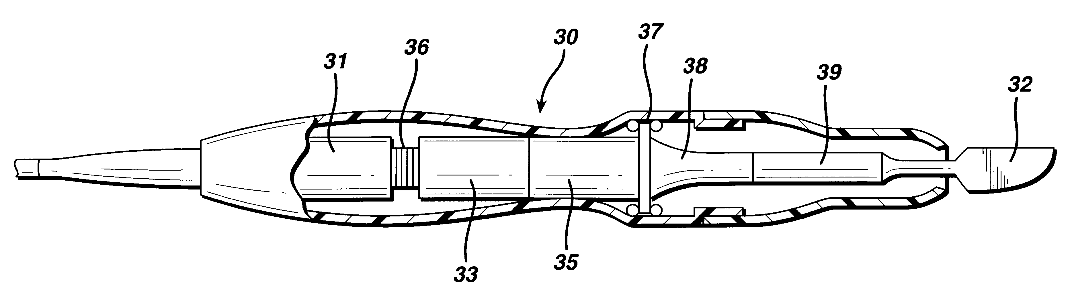
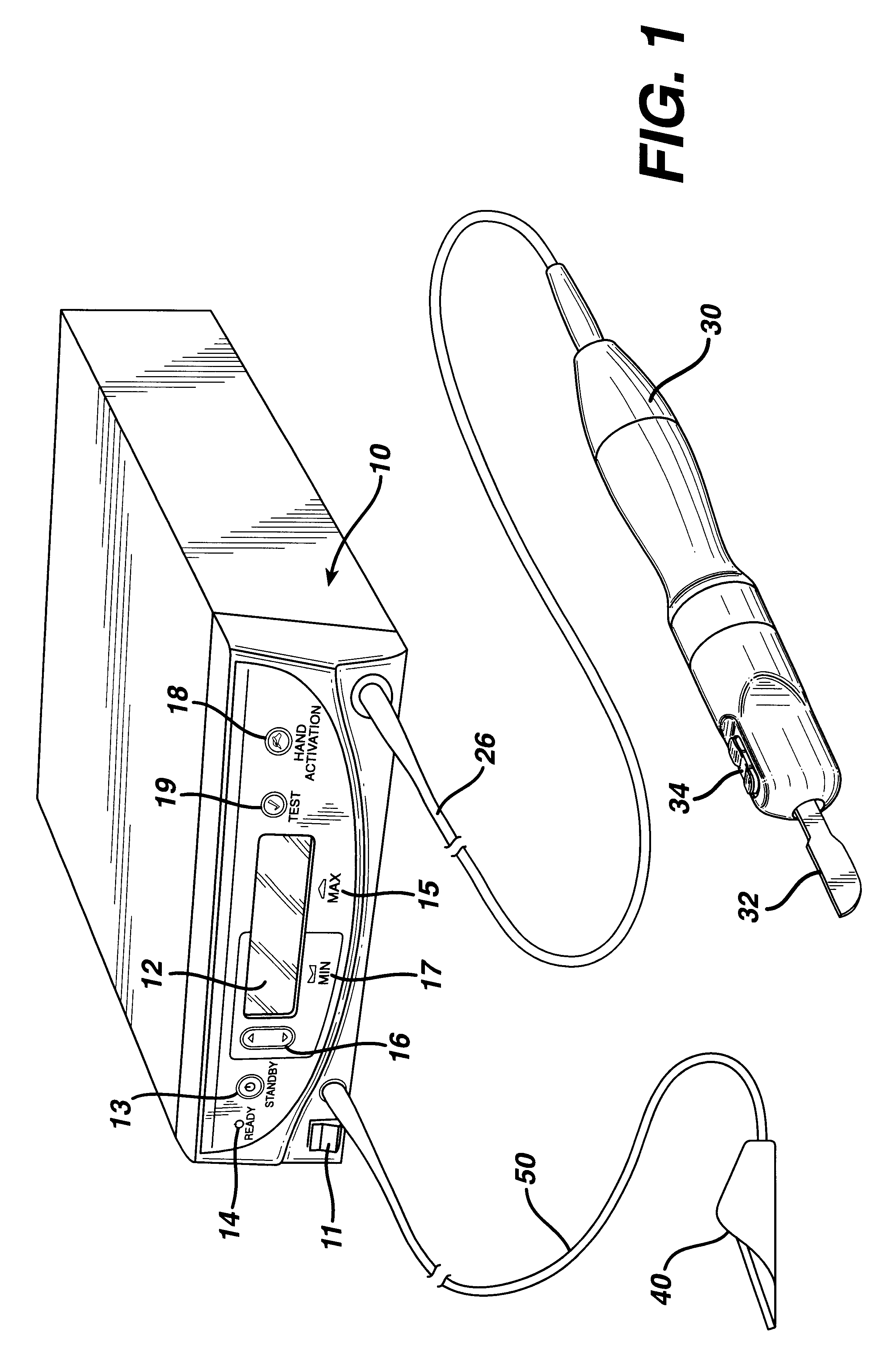
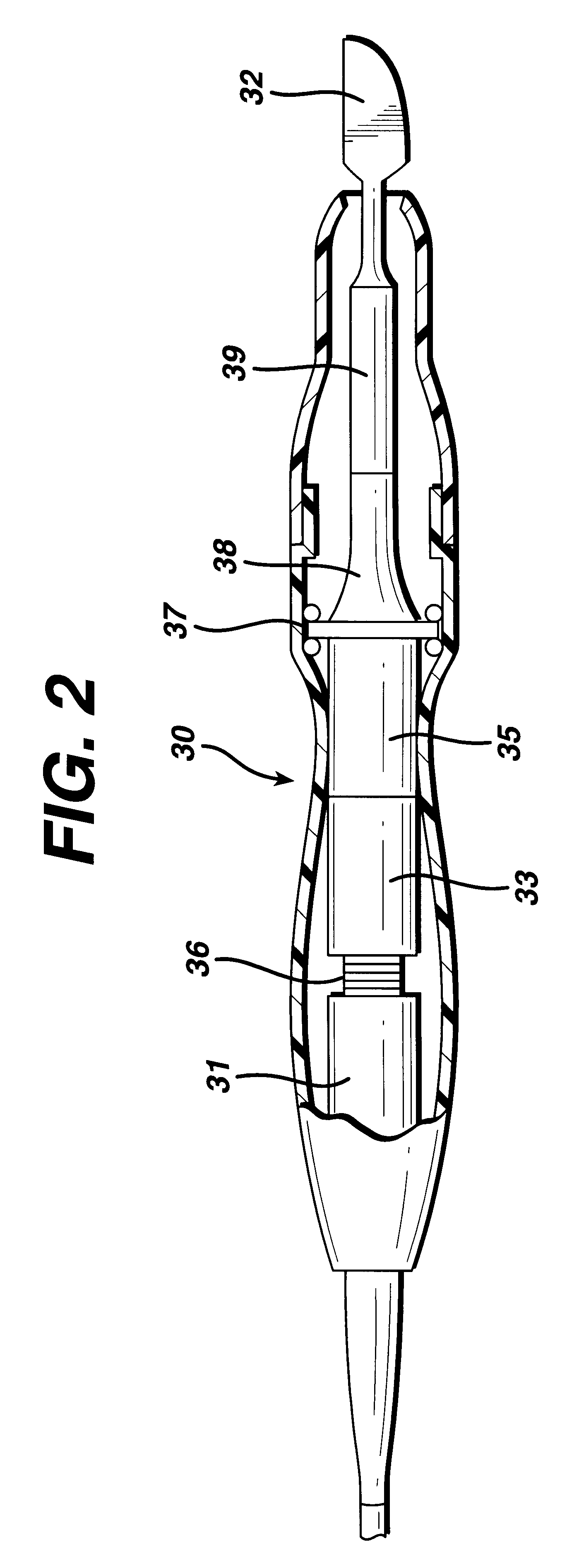
FIG. 1 is an illustration of a system for implementing the method in accordance with the invention. By means of a first set of wires in cable 20, electrical energy, i.e., drive current, is sent from the console 10 to a hand piece 30 where it imparts ultrasonic longitudinal movement to a surgical device, such as a blade 32. This blade can be used for simultaneous dissection and cauterization of tissue. The supply of ultrasonic current to the hand piece 30 may be under the control of a switch 34 located on the hand piece, which is connected to the generator in console 10 via wires in cable 20. The generator may also be controlled by a foot switch 40, which is connected to the console 10 by another cable 50. Thus, in use a surgeon may apply an ultrasonic electrical signal to the hand piece, causing the blade to vibrate longitudinally at an ultrasonic frequency, by operating the switch 34 on the hand piece with his finger, or by operating the foot switch 40 with his foot.

The generator c...


PUM

PropertyMeasurementUnit
frequencyaaaaaaaaaa
diameteraaaaaaaaaa
currentaaaaaaaaaa

Abstract

A method for detecting transverse mode vibrations in an ultrasonic hand piece / blade for determining the existence of unwanted vibration in the hand piece / blade. A tracking filter centered at the drive frequency of the generator, is used to monitor the drive frequency of the ultrasonic generator and attenuate the drive signal when it exceeds a predetermined level. The tracking filter has a wide pass band. Alternatively, a tracking filter having a pass band which is divided into several regions is used to avoid other longitudinal resonances, such as a resonance at a second harmonic, or other spectral features that would otherwise detract from the tracking accuracy of the filter.

Description

1. Field of the InventionThe present invention generally relates to ultrasonic surgical systems and, more particularly, to a method for detecting transverse vibrations in an ultrasonic hand piece / blade.2. Description of the Related ArtIt is known that electric scalpels and lasers can be used as a surgical instrument to perform the dual function of simultaneously effecting the incision and hemostatis of soft tissue by cauterizing tissues and blood vessels. However, such instruments employ very high temperatures to achieve coagulation, causing vaporization and fumes as well as splattering, which increases the risk of spreading infectious diseases to operating room personnel. Additionally, the use of such instruments often results in relatively wide zones of thermal tissue damage.Cutting and cauterizing of tissue by means of surgical blades vibrated at high speeds by ultrasonic drive mechanisms is also well known. One of the problems associated with such ultrasonic cutting instruments ...

Claims


Application Information

Patent Timeline
Patent Type & Authority Patents(United States)
IPC IPC(8): A61B17/32A61B17/00A61B18/00
CPCA61B17/320068A61B2017/00106A61B2017/00123G01N2291/02881A61B2017/320069A61B2017/320071A61B2017/320089
Inventor GIORDANO, JAMES R.STULEN, FOSTER B.
Owner ETHICON ENDO SURGERY INC
Why Eureka
Try Eureka