H-bridge drive circuit for step motor control

a step motor and drive circuit technology, applied in the direction of control systems, electrical apparatus, dynamo-electric converter control, etc., can solve the problems of complex integration of such two-motor systems, inability to achieve the same or better performance at either speed, and cost at least double that of a single-motor system, so as to improve the performance of a single step motor design, cost reduction is significant, and the implementation is simple

Inactive Publication Date: 2011-10-06
LIN ENG INC
View PDF8 Cites 954 Cited by
  • Summary
  • Abstract
  • Description
  • Claims
  • Application Information

AI Technical Summary

Benefits of technology

[0006]A single step motor is driven in accord with the present invention by a unique H-bridge drive circuit that provides a choice of both series and parallel connections to the same bifilar windings and switches between the two types of connections according to the motor speed. When a slow motor speed is required, the H-bridge drive circuit in accord with the present invention connects the bifilar windings in series for optimum performance at that slow speed, and when a high motor speed is required from that same motor, the H-bridge drive circuit connects the same bifilar windings in parallel for optimum performance at that high speed also. The H-bridge drive circuit has a first set of transistors driven by configuration signals and functioning as series / parallel winding configuration transistors, and also has a second set of transistors driven by motor phase signals and connected to step motor coils, where the first set of transistors are arranged to connect a power supply in either series or parallel to the coils through the second set of transistors. Both series and parallel configurations share the power FETs in the H-bridge drive circuit. The switching between winding configurations by the drive circuit can thus provide improved performance of a single step motor design over a wider range of operational motor speeds. This eliminates the requirement for multiple distinct motors and likewise for multiple drive electronics. A single motor system is simpler to implement and costs are significantly reduced.

Problems solved by technology

Only rarely can a motor design be made suitable for both low- and high-speed operation, and these designs usually fail to get the same or better performance at either speed than a motor design that has been optimized for a specific speed.
The integration of such two-motor systems is complex, and costs are at least doubled over that of a single-motor system.

Method used


Image

  • H-bridge drive circuit for step motor control
  • H-bridge drive circuit for step motor control
  • H-bridge drive circuit for step motor control

Examples


Embodiment Construction

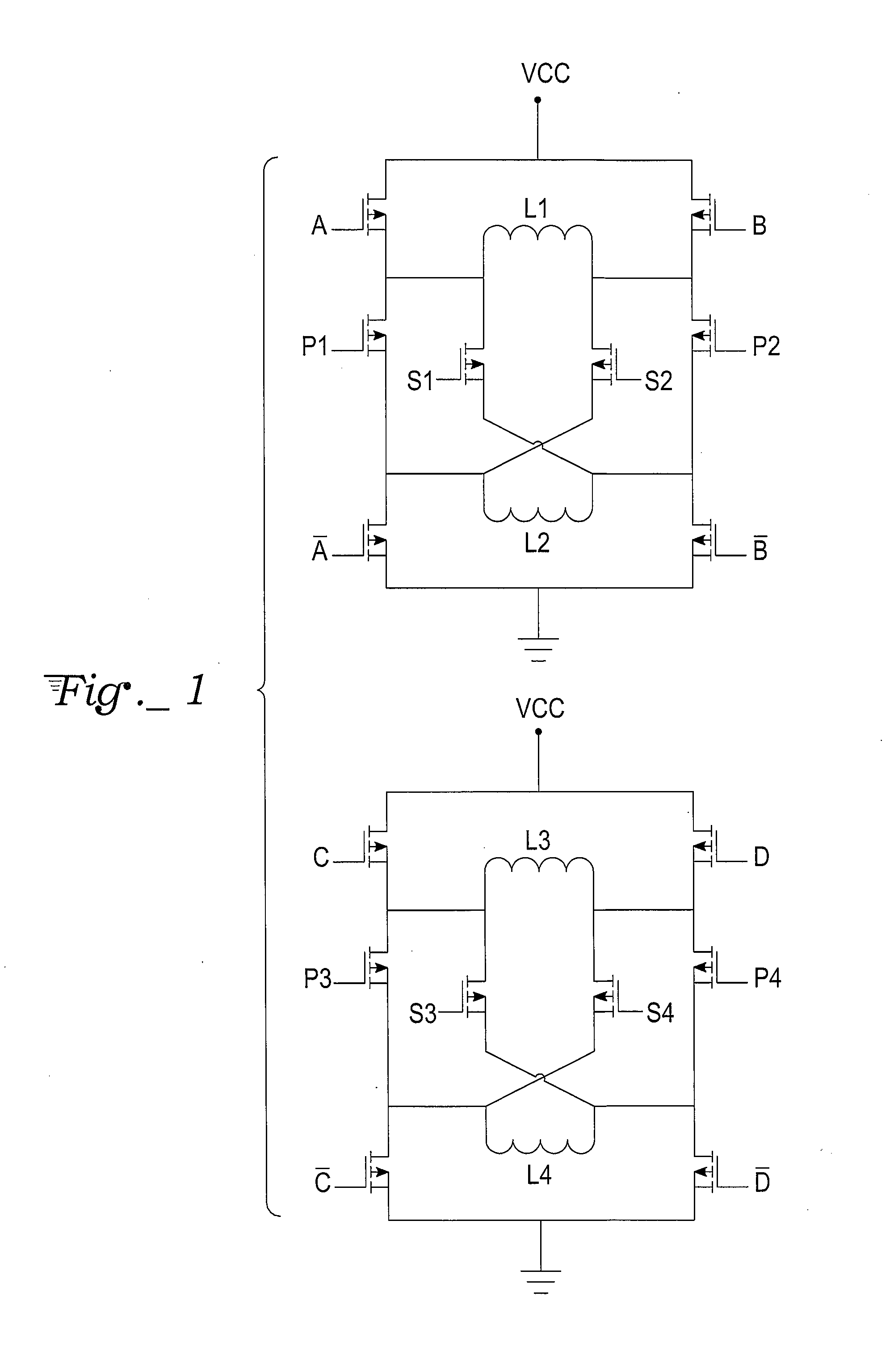
[0015]With reference to FIG. 1, an H-bridge drive circuit for a step motor with bifilar windings has a plurality of identical drive sub-circuits, one for each of the pairs of stator coils of the bifilar windings. In the case where two sets of stator poles are separately wound with pairs of stator coils, the drive circuit has two identical parts or sub-circuits, one for a first pair of step motor stator coils, L1 and L2, with their associated set of driver connections, A, −A, B, and −B, and the other for a second pair of step motor stator coils, L3 and L4, with their associated set of driver connections, C, −C, D and −D. Both parts have control inputs S1, S2, and P for selectively establishing serial or parallel connections of the step motor stator coils.

[0016]The first part of the drive circuit includes a first transistor A coupled to a first power supply terminal Vcc and to a first terminal of a first step motor stator coil L1. A second transistor B is coupled to the first power su...


PUM


Abstract

A drive circuit for step motors with bifilar windings is provided in which both parallel and series winding configurations for the stator coils are selectable by a motor controller based on the motor speed. For low speeds a series configuration is selected, while for higher speeds a parallel configuration is selected. Dynamic torque is optimized by the selection for more efficient motor operation with less drive current.

Description

TECHNICAL FIELD[0001]The present invention relates to step motor controllers and drivers for directing the switching of current among the several stator coils in a cycle of phases, and relates in particular to H-bridge drive circuits and associated winding configurations for obtaining adequate efficiency and motor torque for various motor speeds.BACKGROUND ART[0002]Step motors are used in a wide variety of applications that require precise motion control, such as printers, scanners, x-y tables, turntables, tape and disk drive systems, security cameras and other optical equipment, robotics, electro-mechanical motion control systems, CNC (computer-numeric-control) machine tools, dispensers, injector pumps and other medical equipment. A wide variety of step motor designs and drive circuitry have been introduced in order to achieve specific performance goals, such as reduced noise and vibration, increased resolution and accuracy of motor positions, adequate holding torque, and efficient...

Claims


Application Information

Patent Timeline
Patent Type & Authority Applications(United States)
IPC IPC(8): H02P8/14
CPCH02P8/16H02P8/12
Inventor ZHU, ZHENGMAOKIM, JONGWONABBASSIAN, KAYVAN
Owner LIN ENG INC
Why Eureka
Try Eureka