Molding apparatus for rotor of motor

a technology for rotors and motors, applied in the direction of dynamo-electric components, other domestic articles, coatings, etc., can solve the problems of swollen cores, lower flatness and parallelism of rotor cores made by stacking thin plates, etc., to increase the number of stacked sheets, reduce gap, and increase coupling force

Active Publication Date: 2016-06-14
HYUNDAI MOTOR CO LTD +1
View PDF12 Cites 0 Cited by
  • Summary
  • Abstract
  • Description
  • Claims
  • Application Information

AI Technical Summary

Benefits of technology

[0016]The molding apparatus for a rotor of a motor according to the present disclosure has the following effects.
[0018]That is, as compared with an embossed core, the bond core can increase the number of stacked sheets, reduce a gap between the stacked sheets, and increase coupling force when the same stack thickness is applied, and can reduce iron loss and increase mechanical strength.
[0019]Further, the sizes of inner and outer diameters, and the shape tolerance of the bond core are excellent as compared with an existing embossed core.
[0020]Second, deformation of the core can be improved after a molding process by improving performance of a single product core.
[0021]That is, because the deformations of the inner and outer diameters and the shape tolerance of the core are small as compared with the embossed core, durability performance of the core can be improved due to a decrease in residual stress, an NVH such as a torque ripple can be improved by making the tolerances uniform through improvement of the tolerance of the outer shape, a design can be stabilized through an electromagnetic analysis design and reduction of the performance difference of the actual product, and assembly quality can be secured through management of pressing degree and tolerances.

Problems solved by technology

However, the flatness and parallelism of a rotor core made by stacking thin plates are lower than those of a precise product due to incomplete attachment of the thin plates caused by embossing for a thickness deviation of a thin plate of the core and stacking of the thin plates.
However, after the product is extracted, the core is swollen again by incomplete adhesion of the thin plates due to embossing (spring back).

Method used


Image

  • Molding apparatus for rotor of motor
  • Molding apparatus for rotor of motor
  • Molding apparatus for rotor of motor

Examples


Embodiment Construction

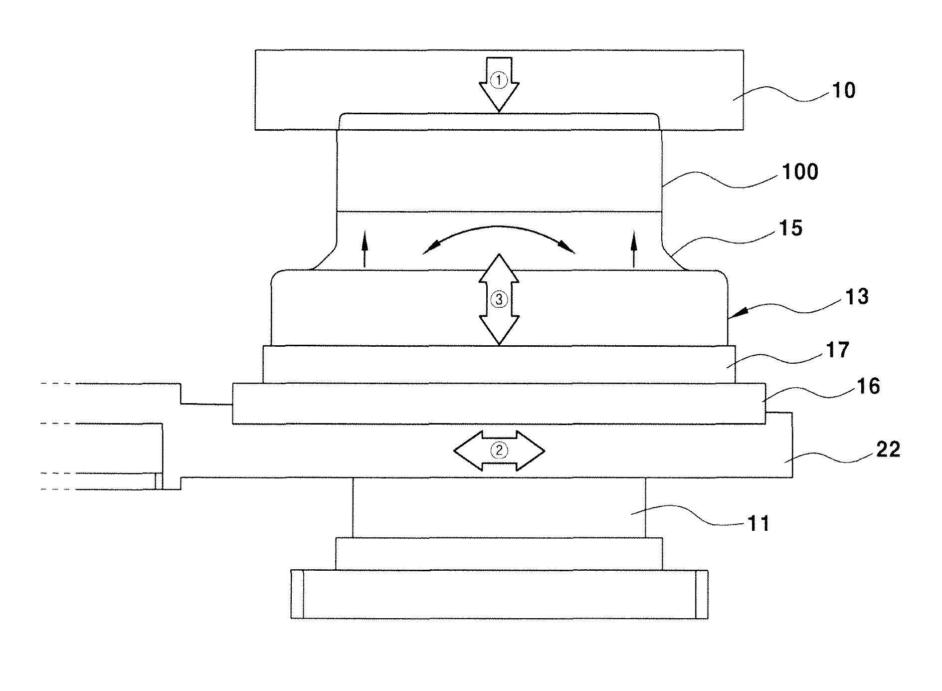
[0031]The present disclosure has been made in an effort to solve the above-mentioned problems. To this end, the present provides a molding process for a rotor of a motor which can reduce manufacturing costs through alleviation of a tolerance of an introduced product and reduction of an error rate of a finished injection-molding product, by applying a lift core which may variably move in a mold during an insert injection molding process for molding a rotor and accordingly a new type of rotor molding method for a permanent magnet synchronous motor which prevents generation of a flash in an injection molding process even when the size and tolerance of the introduced product deteriorate as compared with a mold.

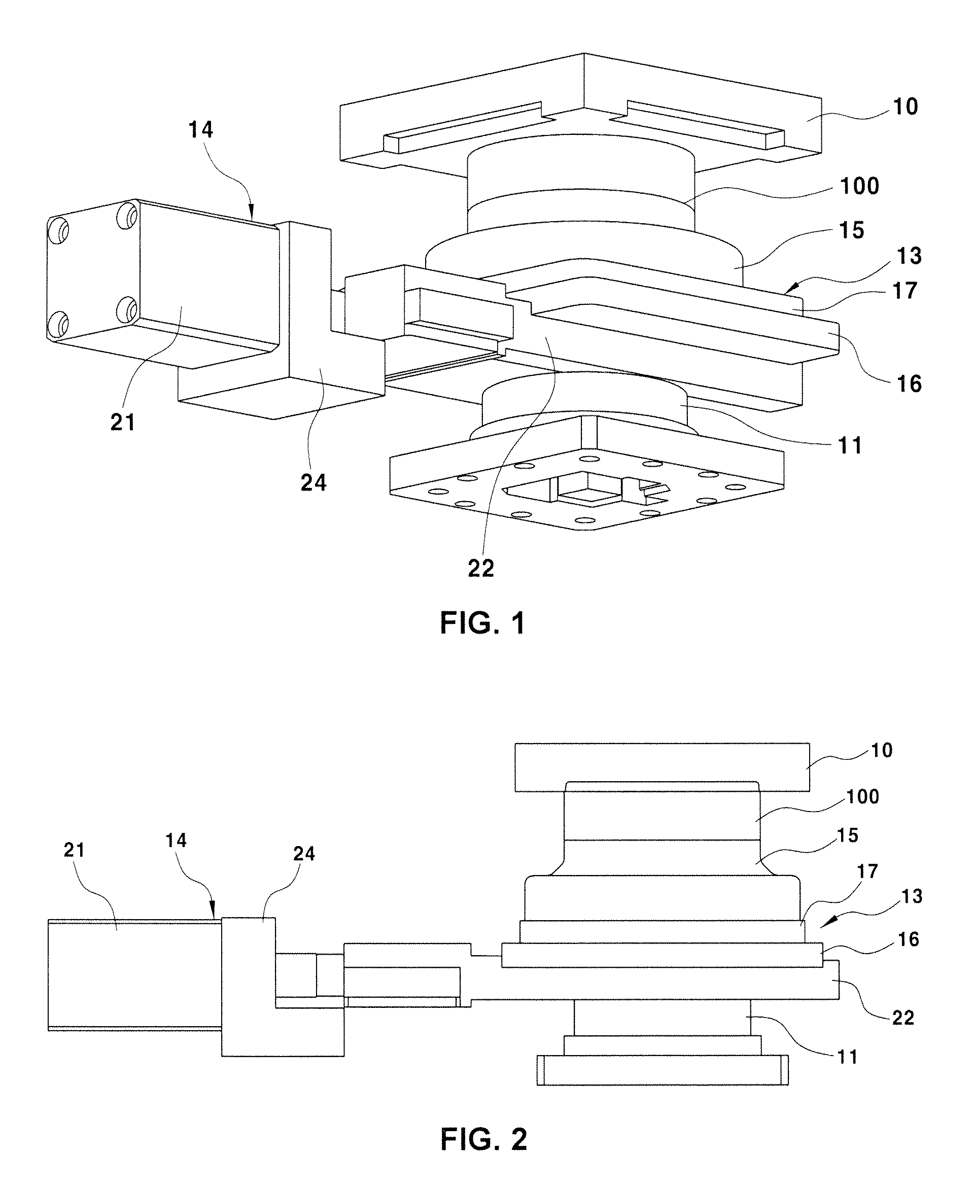
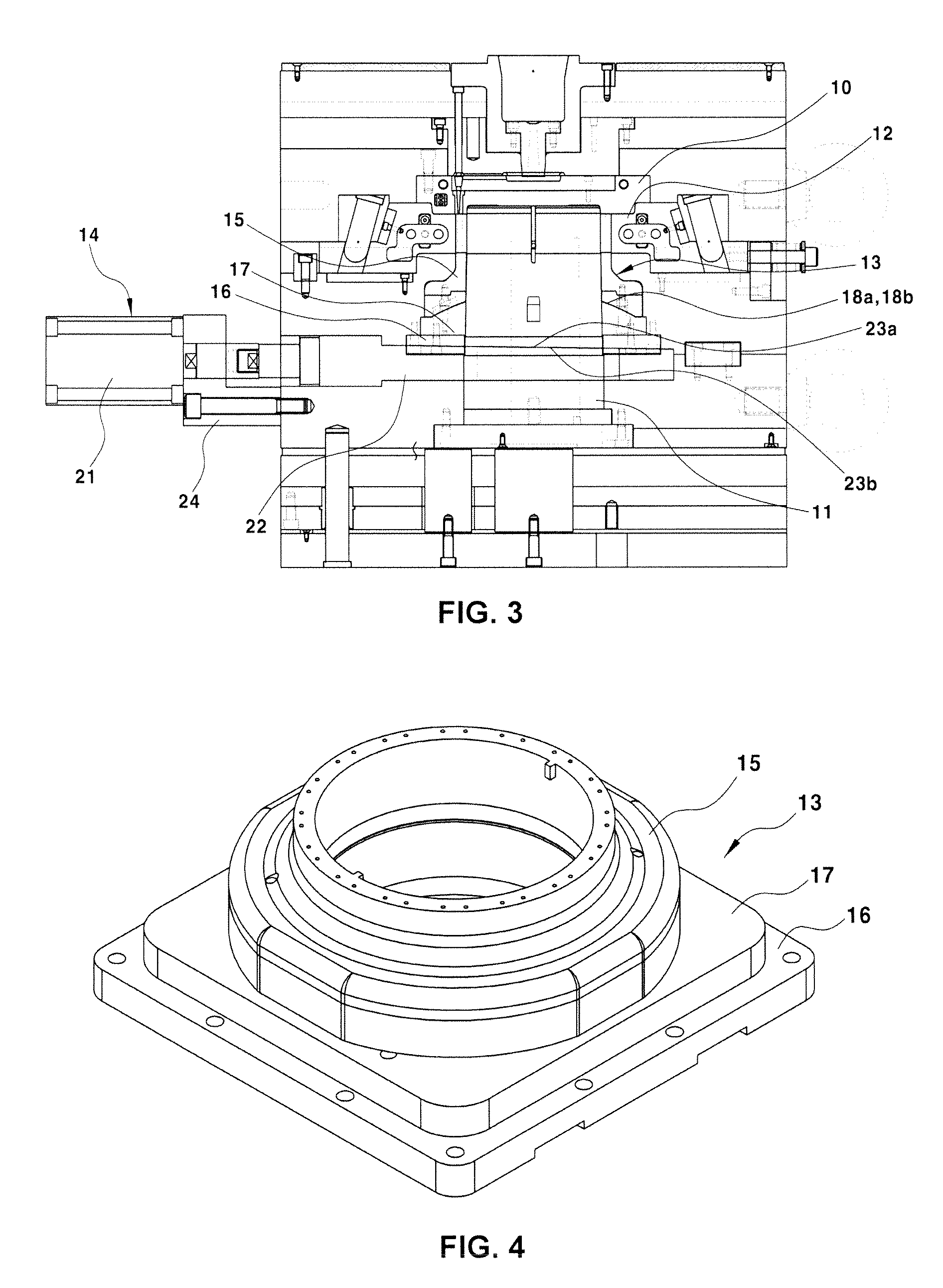
[0032]In order to achieve the above-described objects, the molding apparatus for a rotor of a motor according to the present disclosure has the following features. Hereinafter, the present disclosure will be described in detail with reference to the accompanying drawings.

[0033]FIG...


PUM

PropertyMeasurementUnit
thicknessaaaaaaaaaa
sizeaaaaaaaaaa
shape toleranceaaaaaaaaaa

Abstract

The present disclosure relates to a molding apparatus for fixing a magnet in a rotor core of a permanent magnet synchronous motor. The present disclosure provides a molding process for a rotor of a motor which can reduce manufacturing costs through alleviation of a tolerance of an introduced product and reduction of an error rate of a finished injection-molding product, by applying a lift core which may variably move in a mold during an insert injection molding process for molding a rotor and accordingly a new type of rotor molding method for a permanent magnet synchronous motor which prevents generation of a flash in an injection molding process even when the size and tolerance of the introduced product deteriorate as compared with a mold.

Description

CROSS-REFERENCE TO RELATED APPLICATION[0001]This application claims under 35 U. S. C. §119(a) the benefit of Korean Patent Application No. 10-2014-0064986 filed on May 29, 2014, the entire contents of which are incorporated herein by reference.BACKGROUND[0002](a) Technical Field[0003]The present disclosure relates to a molding apparatus for a rotor of a motor, and more particularly to a molding apparatus for fixing a magnet in a rotor core of a permanent magnet synchronous motor.[0004](b) Background Art[0005]In general, a driving motor as a power source is used in environmental vehicles such as hybrid electric vehicles or electric vehicles. Like a general motor, the driving motor includes a stator in which a coil is wound on a stator coil, and a rotor disposed within the stator and in which a permanent magnet is inserted into a rotor core.[0006]In general, in order to fix a permanent magnet to the rotor core, a method of applying a bond to a permanent magnet insertion hole of a roto...

Claims


Application Information

Patent Timeline
Patent Type & Authority Patents(United States)
IPC IPC(8): B29C45/14B29L31/00
CPCB29C45/14065B29C45/1459B29L2031/7498H02K15/03
Inventor KIE, JAE YOUNGLEE, JUNG WOOSUNG, KWANG KEYONG
Owner HYUNDAI MOTOR CO LTD
Why Eureka
Try Eureka