Gas turbine and exhaust gas diffuser thereof

一种燃气轮机、扩散器的技术,应用在机器/发动机、动力装置的排气口、贮汽器等方向,能够解决导向体长、不考虑支承柱空气动力等问题,达到降低振动、高强度的效果

Inactive Publication Date: 2015-03-04
SIEMENS AG
View PDF7 Cites 0 Cited by
  • Summary
  • Abstract
  • Description
  • Claims
  • Application Information

AI Technical Summary

Problems solved by technology

However, it is disadvantageous that the guide body is relatively long and must therefore be supported by additional struts due to its length
Furthermore, the aerodynamic effects of the support columns are not considered

Method used


Image

  • Gas turbine and exhaust gas diffuser thereof
  • Gas turbine and exhaust gas diffuser thereof
  • Gas turbine and exhaust gas diffuser thereof

Examples


Embodiment Construction

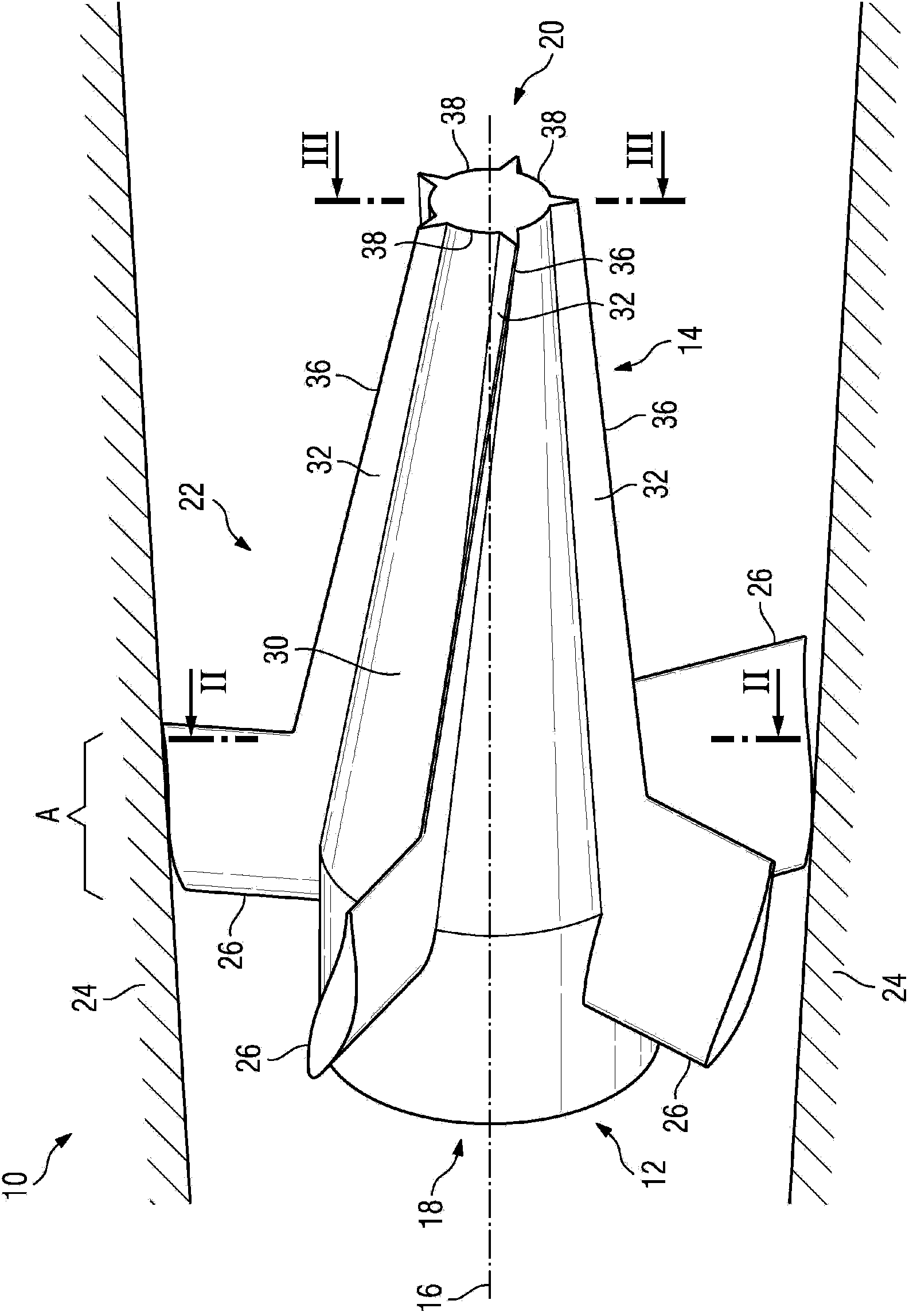
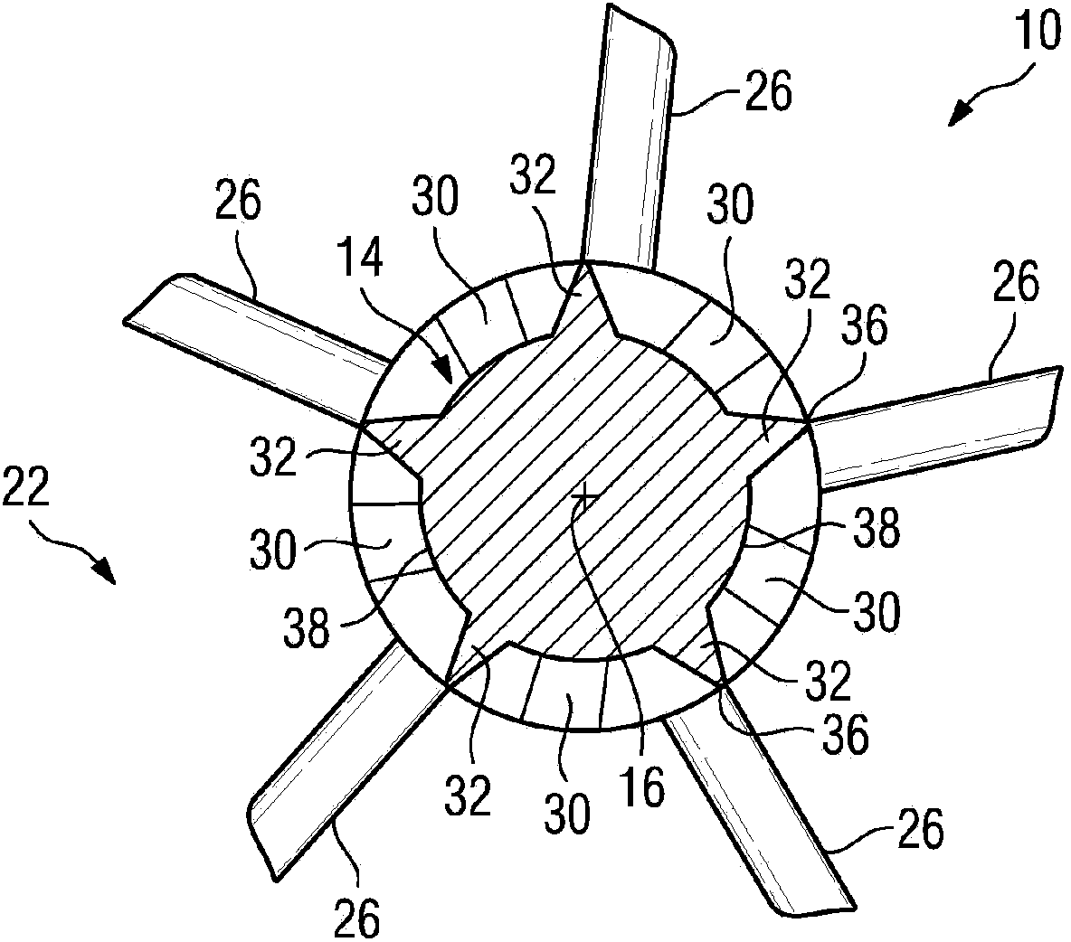
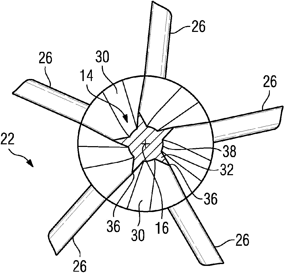
[0017] exist figure 1 shows a longitudinal sectional view of an exhaust diffuser 10 for a gas turbine, wherein a perspective view of a star-shaped support 12 arranged in the center of the exhaust diffuser 10 is shown for the turbine-side The gas turbine rotor and the guide body 14 arranged on the star support are supported. The exhaust gas diffuser 10 has a centrally located center axis 16 which extends from an inflow-side end 18 to an outflow-side end 20 . A flow channel 22 is provided in the exhaust gas diffuser 10 , the cross section of which flow channel is perpendicular to the center axis and has an annular contour. In this case, the flow channel 22 is delimited by a radially outer outer wall 24 . The guide body 14 is arranged in the center of the exhaust gas diffuser 10 , ie in the region of its center axis 16 , and here is the radially inner boundary of the flow channel 22 . In this case, the guide body 14 is supported by five bearing struts 26 distributed uniformly ...


PUM


Abstract

#CMT# # / CMT# The diffuser (10) has a flow channel (22) expanded to a diffuser outlet, and an axially extending conducting body (14) provided at center of the diffuser outlet. The conducting body comprises multiple slots (30) that are distributed over circumference and formed among multiple conducting elements (32) in an axial section of longitudinal extension of the conducting body. The body has a cross-sectional contour arranged perpendicular to a center axis (16) of the diffuser and formed in star shape. Teeth of the body are formed by respective conducting elements. #CMT#USE : # / CMT# Exhaust gas diffuser for a gas turbine. #CMT#ADVANTAGE : # / CMT# The conducting body comprises slots that are distributed over the circumference and formed between the conducting elements in the axial section of the longitudinal extension of the conducting body, so that improvement of pressure recovery can be achieved while allowing homogeneous inflow of hot gas from a gas turbine in a heat recovery steam generator downstream to the gas turbine, thus improving the efficiency of the gas turbine. The conducting body has higher rigidity, so that aerodynamical disturbance and leak out-lateral support of the conducting body can be avoided. #CMT#DESCRIPTION OF DRAWINGS : # / CMT# The drawing shows a partial sectional perspective view of an exhaust gas diffuser of a gas turbine with a conducting body. 10 : Exhaust gas diffuser 14 : Axially extending conducting body 16 : Center axis 22 : Flow channel 30 : Slots 32 : Conducting elements.

Description

technical field [0001] The invention relates to an exhaust diffuser for a gas turbine, the exhaust diffuser has a flow channel widening toward the diffuser outlet, and an axially extending guide body is provided in the center of the exhaust diffuser. Background technique [0002] Such exhaust diffusers are used to decelerate the gas turbine exhaust flow and to recover at least a portion of the dynamic pressure. In order to obtain an exhaust gas diffuser with a relatively large opening angle of 10° or more, it is known, for example, from DE 198 05 115 A1 to provide an axially extending guide body in the center of the diffuser channel. By using the guide body, the exhaust gas diffuser is configured as an annular diffuser. As a result, a larger area of ​​the recirculation zone behind the gas turbine hub is avoided, which has a favorable effect on the efficiency of the exhaust gas diffuser. However, it is disadvantageous that the guide body is relatively long and must therefor...

Claims


Application Information

Patent Timeline
Patent Type & Authority Patents(China)
IPC IPC(8): F01D25/30F01K1/04F01D25/16B64D33/04F02K1/82F01D5/14
CPCF01D5/145F05D2250/15F05D2250/25F01D25/30F02K1/04
Inventor 马克·布勒克托比亚斯·布哈尔
Owner SIEMENS AG
Why Eureka
Try Eureka