Rack and pinion steering unit

A technology of rack and pinion and steering gear, which is applied in the direction of steering gear, mechanical steering gear, steering mechanism, etc., and can solve the problems of steering wheel operation force fluctuation, manufacturing error, and inability to properly maintain the meshing state of pinion teeth and rack teeth. , to achieve the effect of preventing the operating force and improving the response performance

Inactive Publication Date: 2015-12-09
NSK LTD
View PDF5 Cites 0 Cited by
  • Summary
  • Abstract
  • Description
  • Claims
  • Application Information

AI Technical Summary

Problems solved by technology

[0013] In this structure, since the inclined surface of the rack shaft is biased in the axial direction of the rack shaft, the rack shaft may be inclined with respect to the axis.
In addition, there may be manufacturing errors between the respective tapered surfaces of the pressing rollers divided into two, or gaps may occur between the inner peripheral surface of the pressing roller and the outer peripheral surface of the support shaft.
Therefore, in the case of this structure, due to the above-mentioned phenomenon, the meshing state of the meshing portion of the pinion teeth and the rack teeth cannot be properly maintained. sense of incongruity
If the meshing state of the meshing portion of the pinion teeth and the rack teeth deviates significantly from the proper state, damage, etc., may occur at the meshing portion due to a local collision.

Method used


Image

  • Rack and pinion steering unit
  • Rack and pinion steering unit
  • Rack and pinion steering unit

Examples


Embodiment Construction

[0045] [First example of embodiment of the present invention]

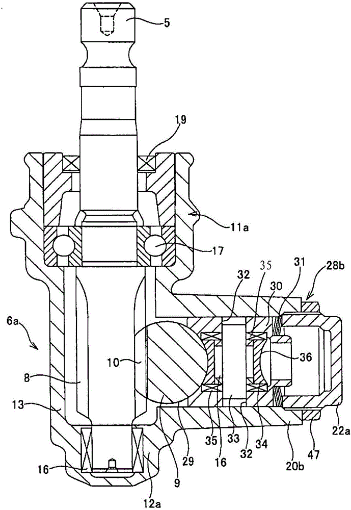
[0046] Figure 1 ~ Figure 2 The first example of the embodiment of the present invention is shown. The steering gear unit 6a of this example is attached to an unillustrated vehicle frame such as a front subframe. figure 1 above is the upper side of the vehicle body, figure 1 The lower side is the lower side of the vehicle body, figure 1 The left and right direction is the vehicle body width direction, figure 1 The direction perpendicular to the paper surface is the front and rear direction of the vehicle body. In addition, materials and the like of members constituting the rack and pinion steering unit according to the present invention, including this example, are the same as conventional ones unless otherwise specified.

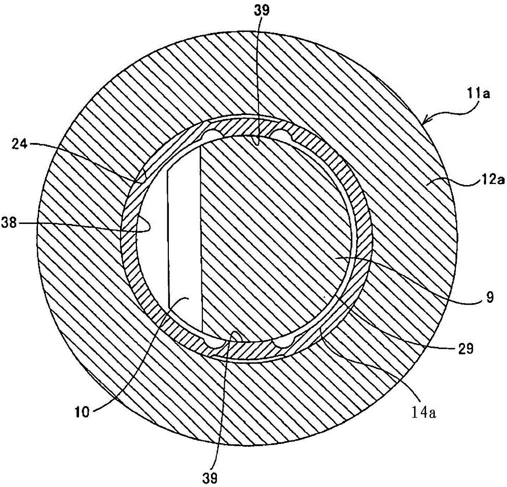
[0047] The rack shaft 9 is displaceably fitted in the inner peripheral surface 24 of the main housing portion 12a of the case 11a of the steering gear unit 6a in the vehicle width dire...


PUM


Abstract

A rack and pinion steering gear unit is achieved that is capable of preventing an increase in operating force of the steering wheel and auxiliary operating force from a motor, and improving the response performance to minute operation when traveling straight. A pressing roller 34 elastically pushes the rear surface 29 of a rack shaft 9 toward a pinion shaft 5. This pressing roller 34 is supported by way of a radial needle bearing 16a by a support shaft 33 that is supported by and fastened to a holder 30 so as to be able to rotate freely. A thrust needle bearing 35 that receives a thrust load that is applied to the pressing roller 34 is provided between both side surfaces in the axial direction of the pressing roller 34 and the inside surface of the holder 30.

Description

technical field [0001] The present invention relates to a rack and pinion steering unit constituting a steering device for applying a steering angle to steering wheels of an automobile, and more particularly to a rack and pinion steering unit using a rolling rack guide. Background technique [0002] As a mechanism for converting rotational motion input from a steering wheel into linear motion for applying a steering angle, a rack and pinion steering unit is used. Steering devices equipped with rack and pinion steering gear units are described in Japanese Patent Application Laid-Open No. 2009-184591, Japanese Patent Laid-Open No. 2004-17872, Japanese Patent Application Laid-Open No. 61-124471, etc., and conventionally widely known. [0003] Figure 7 An example of a steering device incorporating a rack and pinion steering unit is shown. This steering device is a so-called column assist type rack and pinion power steering device. That is, in order to reduce the operating fo...

Claims


Application Information

Patent Timeline
Patent Type & Authority Patents(China)
IPC IPC(8): B62D3/12F16H19/04
CPCB62D3/123F16H55/285Y10T74/18096
Inventor 天田慎也新井利幸
Owner NSK LTD
Why Eureka
Try Eureka