Continuously variable transmission devices

A technology of continuously variable transmission and variable speed transmission, which is applied in belts/chains/gears, mechanical equipment, transmission devices, etc. It can solve the problems of power reduction, poor resistance to overload and impact resistance, and low load-carrying capacity, so as to achieve stable output power, The effect of wide speed range and simple structure

Active Publication Date: 2015-04-29
SOUTH CHINA AGRI UNIV
View PDF6 Cites 0 Cited by
  • Summary
  • Abstract
  • Description
  • Claims
  • Application Information

AI Technical Summary

Problems solved by technology

Hydraulic transmission has high requirements on the manufacturing precision of the transmission, the price is relatively expensive, the output characteristic is constant torque, the slip rate is large, and oil leakage is prone to occur during operation; the mechanical transmission has high requirements on the processing and lubrication of transmission parts, and the carrying capacity is relatively high. Low, poor overload resistance and impact resistance, small effective speed range, generally suitable for medium and small power transmission; the transmission of electric transmission is mainly AC motor type, constant torque output at low speed when the frequency is reduced, and the power is reduced
Generally speaking, the current continuously variable transmission has complex structure, high process requirements, and local performance needs to be improved

Method used


Image

  • Continuously variable transmission devices
  • Continuously variable transmission devices
  • Continuously variable transmission devices

Examples


Embodiment 1

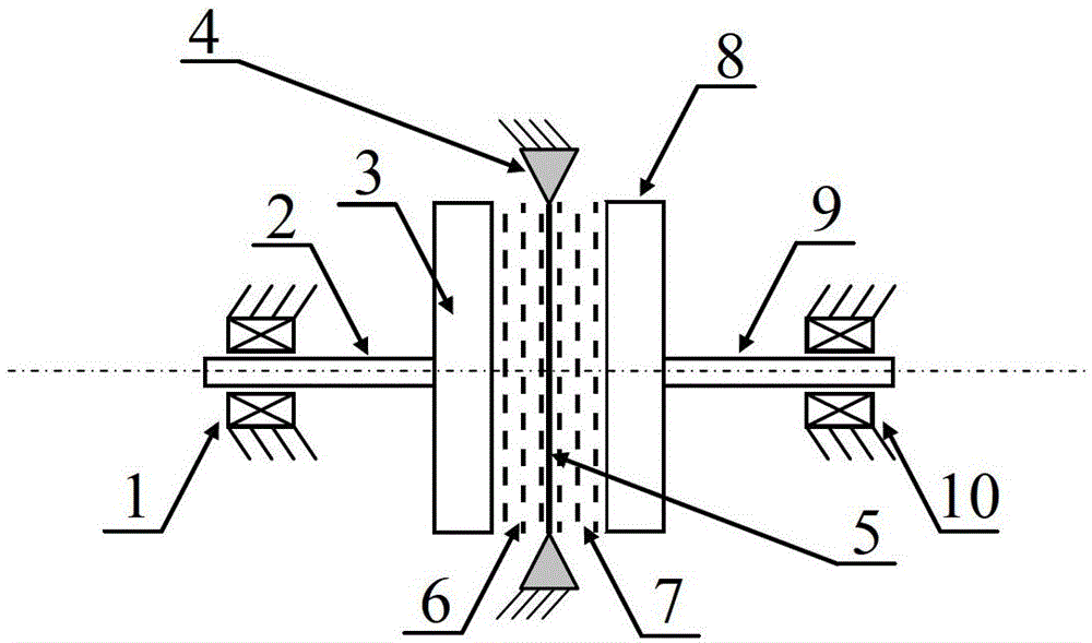
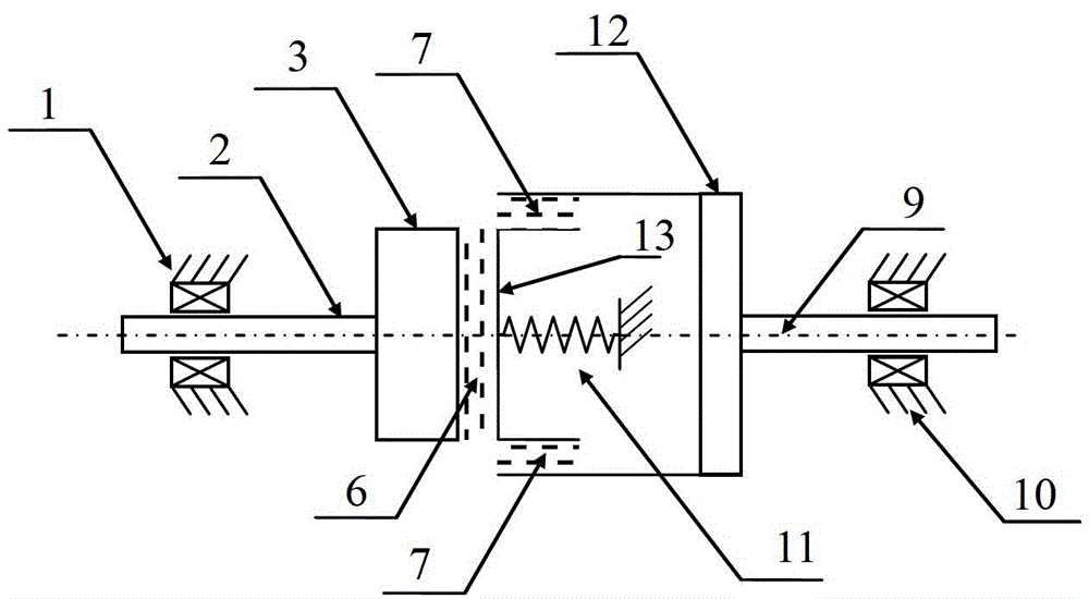
[0042] like figure 1 shown. A continuously variable transmission, comprising an input system, a variable speed transmission system and an output system arranged in series coaxially; The system includes an elastic mechanism 4, a transmission disc 5, a class I medium 6 and a class II medium 7, wherein the class I medium 6 and the class II medium 7 are electrorheological fluids; the output system includes a class II energy storage flywheel 8, an output shaft 9 and the output shaft locating bearing 10; the input shaft locating bearing 1 is embedded with the input shaft 2 to fix the input shaft 2, and the input shaft 2 is coaxially rigidly connected with the heavy I-level energy storage flywheel 3; the I-level energy storage A class I medium 6 is placed between the flywheel 3 and the drive disc 5, and a class II medium 7 is placed between the drive disc 5 and the class II energy storage flywheel 8; Under the action of the solid-liquid transition medium, when a voltage or magnetic...

Embodiment 2

[0051] Level I medium 6 and level II medium 7 are electromagnetic fluids, and the others are the same as in Embodiment 1. The surfaces of the I-level energy storage flywheel 3, the II-level energy storage flywheel 8 and the transmission disc 5 are subjected to magnetic isolation treatment.

Embodiment 3

[0053] Level I medium 6 and level II medium 7 are controllable magnetic powders, and the others are the same as in Embodiment 1.


PUM


Abstract

The invention discloses a continuously variable transmission method and two continuously variable transmission devices. The continuously variable transmission method is characterized in that media serve as a high-frequency transmission switch, and conversion of output rotating speed and torque is achieved through a mechanical energy storage mechanism, wherein the media can have solid state and liquid state transformation under effect of voltage or a magnetic field. The mechanical energy storage mechanism is composed of a heavy energy storage flywheel and a light transmission disc, and the media are located between the energy storage flywheel and the transmission disc. When voltage or the magnetic field is exerted, the media are solidified and accordingly integrally connect the energy storage flywheel and the transmission disc, when voltage or the magnetic field disappears, the media are liquefied and accordingly the energy storage flywheel and the transmission disc are not mechanically connected and rotate freely respectively, and control on output rotating speed and torque is achieved by controlling time proportion of media solid state and media liquid state. The two continuously variable transmission devices for achieving the continuously variable transmission method have the advantages of being wide in speed regulating range, fast in response, simple in structure, stable in output power and the like.

Description

technical field [0001] The invention relates to the field of electromechanical integration, in particular to a continuously variable transmission method and a continuously variable transmission. Background technique [0002] The continuously variable transmission can better satisfy the good matching between the electric motor or the engine and the transmission system under the optimal working condition. Traditional continuously variable transmissions are mainly divided into hydraulic transmission, mechanical transmission and electric transmission. Hydraulic transmission has high requirements on the manufacturing precision of the transmission, the price is more expensive, the output characteristic is constant torque, the slip rate is large, and oil leakage is prone to occur during operation; the mechanical transmission has high requirements on the processing and lubrication of transmission parts, and the carrying capacity is relatively high. Low, poor overload resistance and...

Claims


Application Information

Patent Timeline
Patent Type & Authority Patents(China)
IPC IPC(8): F16H33/04
Inventor 闫国琦陈润恩
Owner SOUTH CHINA AGRI UNIV
Why Eureka
Try Eureka