Automatic dimming emergency lamp

A technology for automatic dimming and lamps, which is applied in the direction of emergency power supply arrangements, light sources, electric light sources, etc., which can solve the problems of short lighting time, high power consumption of lamps, and limited emergency battery capacity, etc., to achieve brightness reduction and load The effect of increasing the resistance and reducing the load power

Active Publication Date: 2013-04-10
OCEANS KING LIGHTING SCI&TECH CO LTD +1
View PDF5 Cites 11 Cited by
  • Summary
  • Abstract
  • Description
  • Claims
  • Application Information

AI Technical Summary

Problems solved by technology

[0003] Usually, when the mains power is cut off, when the emergency battery is used for power supply, the lighting intensity is not expected to be the same as when the mains is used, because the power consumed by each lamp is relatively large, and because the capacity of the emergency battery is limited, the lamps Lighting time is relatively short

Method used


Image

  • Automatic dimming emergency lamp
  • Automatic dimming emergency lamp
  • Automatic dimming emergency lamp

Examples


Embodiment Construction

[0020] The following will clearly and completely describe the technical solutions in the embodiments of the present invention with reference to the accompanying drawings in the embodiments of the present invention. Obviously, the described embodiments are only some, not all, embodiments of the present invention. Based on the embodiments of the present invention, all other embodiments obtained by persons of ordinary skill in the art without creative efforts fall within the protection scope of the present invention.

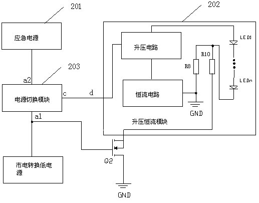
[0021] The present invention realizes the automatic dimming function and lighting delay of the emergency lamp by controlling the size of the load resistance connected to the step-up constant current module, that is, controlling the connection or disconnection of the second load resistance.

[0022] see figure 2 , is a functional block diagram of an embodiment of the automatic dimming emergency lamp of the present invention. The automatic dimming emergency lamp in...


PUM


Abstract

The embodiment of the invention discloses an automatic dimming emergency lamp. The automatic dimming emergency lamp comprises an emergency power supply, a boost constant current module, a power supply switching module and a field effect transistor Q2, a load of the boost constant current module comprises a first load resistor and a second load resistor, two ends of the first load resistor are connected with ground and one end of the second load resistor respectively, the other end of the second load resistor is connected with a source electrode of the field effect transistor Q2, a drain electrode of the field effect transistor Q2 is grounded, a grid electrode of the field effect transistor Q2 is connected with a first input end of the power supply switching module, the first input end of the power supply switching module is connected with a mains supply conversion low power supply, a second input end of the power supply switching module is connected with the emergency power supply, an output end of the power supply switching module is connected with the boost constant current module, the power supply switching module is used for controlling the boost constant current module to access to the mains supply conversion low power supply when a mains supply is normal, the field effect transistor Q2 is connected, when the mains supply is cut off, the power supply is switched to the emergency power supply, and the field effect transistor is disconnected. According to the automatic dimming emergency lamp, the access or cutting off of the second load resistor is controlled through connecting and disconnecting of the Q2, so that the illumination intensity of the emergency lamp is changed, and the illumination time is prolonged.

Description

technical field [0001] The invention relates to an emergency lamp, in particular to an emergency lamp with automatic dimming. Background technique [0002] In order to continue lighting when there is no mains power, an emergency power supply is usually provided to supply power to the lamps after power failure. See figure 1 , which is the circuit schematic diagram of the current emergency lamps. Depend on figure 1 It can be known that when the mains conversion low power supply B2 is connected, the load resistor R and the light-emitting diodes LED1 to LEDn are connected to the circuit, and LED1 to LEDn light up; when the mains conversion low power supply B2 is disconnected, the power supply is switched to The emergency battery B1 supplies power to the entire circuit. At this time, the load resistor R and the light-emitting diodes LED1 to LEDn are also connected to the circuit, and LED1 to LEDn are lit, thereby realizing the function of continuing emergency lighting when the...

Claims


Application Information

Patent Timeline
Patent Type & Authority Applications(China)
IPC IPC(8): H05B37/02H02J9/06
CPCY02B20/40
Inventor 周明杰管伟芳
Owner OCEANS KING LIGHTING SCI&TECH CO LTD
Why Eureka
Try Eureka