IUD (intrauterine device) insertion device

An intrauterine device and placer technology, which is applied in the direction of female contraceptives, etc., can solve the problems that straight push rods and placement tubes cannot adapt to the uterus, large differences in inclination and flexion, etc.

Active Publication Date: 2013-08-21
LIAONING AIMU MEDICAL SCI&TECH
View PDF8 Cites 2 Cited by
  • Summary
  • Abstract
  • Description
  • Claims
  • Application Information

AI Technical Summary

Problems solved by technology

[0003] The IUD placer usually consists of a straight push rod and a straight insertion tube, but the shape of the uterus is differ...

Method used


Image

  • IUD (intrauterine device) insertion device
  • IUD (intrauterine device) insertion device

Examples


Embodiment 1

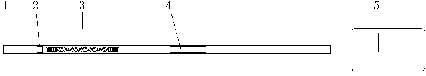
[0016] The intrauterine device placement device is composed of a placement tube 1, a push rod and a handle 5, the push rod is composed of a push rod head 2, a push rod body 4 and a spring 3, and the spring 3 is a flexible spring, which is installed on the push rod body 4 and the Between putter heads 2.

Embodiment 2

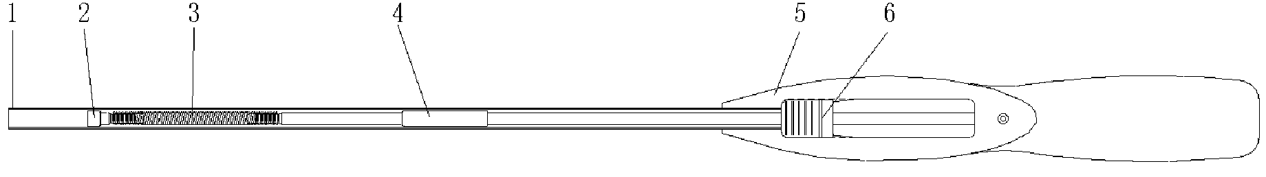
[0018] The intrauterine device placement device is composed of a placement tube 1, a push rod and a handle 5, the push rod is composed of a push rod head 2, a push rod body 4 and a spring 3, and the spring 3 is a flexible spring, which is installed on the push rod body 4 and the Between putter heads 2. The handle 5 is a structure of upper and lower halves, the rear end of the push rod body 4 is fixed with the front end of the handle 5 , and the rear end of the handle 5 is fixed with the slider 6 .


PUM


Abstract

An IUD (intrauterine device) insertion device comprises an insertion tube, a push rod and a handle. The push rod comprises a push rod head, a push rod body and a spring. The spring is arranged between the push rod body and the push rod head. Before insertion of an IUD, the insertion tube of the insertion device can be bent according to the position of uterus so as to adapt to the uterus in shape. When the IUD is conveyed by the push rod having the spring, the push rod can move in correspondence to the shape of the insertion tube while curvature of the insertion tube is prevented from changing due to the rigidity of the insertion tube.

Description

technical field [0001] The invention relates to an intrauterine contraceptive device for women, in particular to a placement device for an intrauterine contraceptive device. Background technique [0002] The intrauterine contraceptive device (referred to as "the IUD") is a contraceptive device placed in the uterine cavity of a woman. [0003] The IUD placer usually consists of a straight push rod and a straight insertion tube, but the shape of the uterus is different, and the inclination varies greatly among individuals, and the straight push rod and insertion tube cannot be adapted to all uteri. Contents of the invention [0004] The purpose of the present invention is to provide an intrauterine device placement device to improve the defects in the known technology. [0005] In order to achieve the above object, the IUD placement device provided by the present invention is composed of a placement tube, a push rod and a handle, the push rod is composed of a push rod head,...

Claims


Application Information

Patent Timeline
IPC IPC(8): A61F6/18
Inventor 武晓锋
Owner LIAONING AIMU MEDICAL SCI&TECH
Why Eureka
Try Eureka