

Rubber ram for cable festoon
A technology of towing and cables, which is applied in the field of lifting equipment, can solve the problems of limited service life and poor buffering effect, and achieve the effects of good buffering effect, long service life and easy manufacture
- Summary
- Abstract
- Description
- Claims
- Application Information
AI Technical Summary
Problems solved by technology
Method used
Image

Examples
Embodiment Construction
[0017] The following descriptions are only preferred embodiments of the present invention, and do not limit the scope of the present invention.
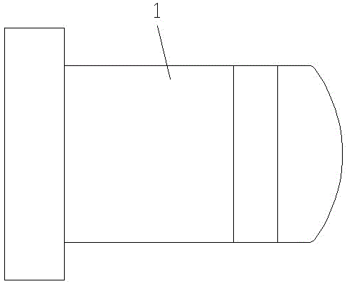
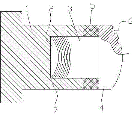
[0018] Examples, see attached figure 1 , 2 , a rubber bumper for cable trolleys, including a rubber column 1, the rubber column is cylindrical and made of hard rubber, a sliding cavity 2 is provided on the rubber column 1, the sliding cavity 2 and an end surface of the rubber column In the same way, the sliding chamber 2 is provided with a piston rod 3, the diameter of the piston rod 3 is 1 / 4-1 / 3 of the diameter of the rubber column 1, and the piston rod is a steel rod or a copper rod, which cannot be too thick. Preferably, the piston rod 3 is provided with a copper ball head 4, the end of the copper ball head 4 is provided with a copper ball head, and the copper ball head is provided with a plurality of pits 6, and the pits 6 are horizontal. The cross-section is arc-shaped, because copper is relatively soft, after multiple impacts...
PUM
 Abstract
Description
Claims
Application Information