Positioning laser marking jig

A laser marking and jig technology, applied in laser welding equipment, manufacturing tools, welding equipment, etc., can solve problems such as inaccurate positioning, inability to mark products at one time, slow speed, etc., to achieve increased efficiency, simple structure, and prevent wear effect

Active Publication Date: 2014-07-30
HAIYAN HATEHUI MACHINERY HARDWARE
View PDF6 Cites 1 Cited by
  • Summary
  • Abstract
  • Description
  • Claims
  • Application Information

AI Technical Summary

Problems solved by technology

In the existing laser marking technology, there are many problems such as inaccurate positioning, inability to mark many products at one time, and slow speed.

Method used


Image

  • Positioning laser marking jig

Examples


Embodiment Construction

[0013] Specific embodiments of the present invention will be further described in detail below.

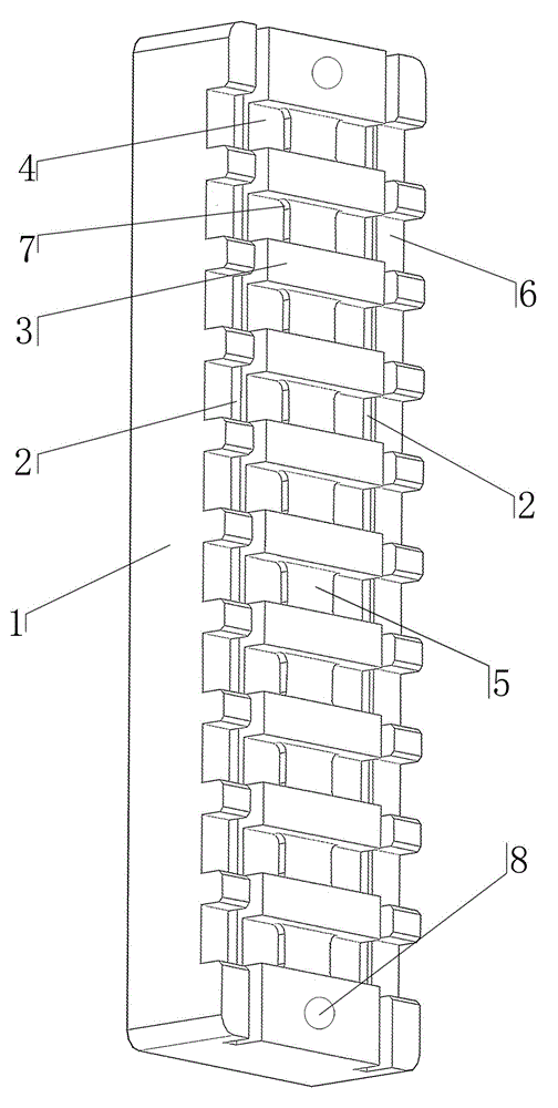
[0014] Such as figure 1 As shown, the positioning laser marking fixture of the present invention includes a long strip-shaped block fixture main body 1, and two parallel strip grooves 2 are provided on both sides of the long side of the fixture main body 1. A plurality of projections 3 perpendicular to the bar-shaped grooves are equidistant between the strip-shaped grooves 2, and positioning grooves 4 for placing workpieces are respectively provided on both sides between the projections 3, and a gap is formed between the two positioning grooves 4. Block 5.

[0015] The outer sides of the two shaped grooves 2 are provided with several block grooves 6, the block grooves 6 are correspondingly arranged with the positioning groove 4, the block grooves 6 are slightly larger than the length of the positioning groove 4, and the protrusions 3. There are at least 9 pieces. The two inner c...


PUM


Abstract

The invention discloses a positioning laser marking jig which comprises a long-strip type block-shaped jig main body, and is characterized in that two parallel strip-type grooves are respectively formed in two sides of the long edge of the jig main body; a plurality of convex blocks perpendicular to the strip-type grooves are arranged between the two strip-type grooves at equal intervals; positioning slots for placing workpieces are respectively formed in two sides between the convex blocks; a stop block is formed between the two positioning slots. The positioning laser marking jig is provided with the multiple convex blocks perpendicular to the strip-type grooves, and the convex blocks are isolated by the positioning slots; the position consistency of the positioning slots is guaranteed; since the multiple block-shaped grooves corresponding to the positioning slots are formed in the outer sides of the two strip-type grooves, products can be conveniently put into and taken out of the positioning slots; same arc chamfers are arranged at two corners on the inner side of each positioning slot, so that the products are protected, and abrasion caused in a laser marking process is prevented. The positioning laser marking jig has the advantages of simple structure, convenience in use and the like, and more products can be marked at a time.

Description

technical field [0001] The invention relates to an auxiliary fixture for marking, in particular to a positioning laser marking fixture. Background technique [0002] Laser marking technology is one of the largest application areas of laser processing. Laser marking is a marking method that uses a high-energy-density laser to locally irradiate the workpiece to vaporize the surface material or undergo a chemical reaction of color change, thereby leaving a permanent mark. Laser marking can print various characters, symbols and patterns, etc., and the character size can range from millimeters to microns, which has special significance for product anti-counterfeiting. In the existing laser marking technology, there are many problems such as inaccurate positioning, inability to mark many products at one time, and slow speed. [0003] Contents of the invention [0004] In order to overcome the above problems, the present invention provides a positioning laser marking jig with ...

Claims


Application Information

Patent Timeline
IPC IPC(8): B23K26/70B23K26/362
CPCB23K26/361B23K26/702
Inventor 周建荣
Owner HAIYAN HATEHUI MACHINERY HARDWARE
Why Eureka
Try Eureka