

Frames for high pressure roller presses
A technology of high-pressure rollers and racks, applied in presses, presses using rotating pressure components, grain processing, etc., can solve the problems of no function, high space requirements for bridge frames, etc., and achieve the effect of avoiding breaking points
- Summary
- Abstract
- Description
- Claims
- Application Information
AI Technical Summary
Problems solved by technology
Method used
Image

Examples
Embodiment Construction
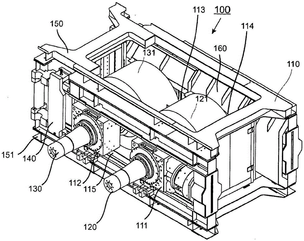
[0013] exist figure 1 A high-pressure roller press 100 with a stand 110 according to the invention is depicted in FIG. Bearing brackets 111 , 112 , 113 and (not visible) 114 sliding on mounts are accommodated in frame 110 , only the front mount 115 is visible in this view. A corresponding bearing is received in each bearing bracket, each bearing rotatably supporting the shafts 120 and 130 of the grinding rollers 121 and 131 .
[0014] In order to remove the grinding rollers 121 and 131 from the frame 110, it is provided in this design that the locking device 140 is taken out of the frame 110 in order to thereby open the machine on the side of the frame pointing backwards from the paper. shelf. The grinding rollers 121 and 131 with their bearings and bearing brackets 111, 112, 113 and 114 are then pushed out of the frame backwards with respect to the paper. The sub-elements or belt structures 150 and 151 remain after the grinding roller has been dismantled and form open open...
PUM
 Abstract
Description
Claims
Application Information