Check patentability & draft patents in minutes with Patsnap Eureka AI!

Screw conveying mechanism of screwdriver for connecting screws and screwdriver for connecting screws

A technology for conveying mechanisms and connecting screws, which can be applied to screwdrivers, wrenches, metal processing equipment, etc., and can solve problems such as increased operating load of driving operations

Active Publication Date: 2019-02-12
MAX CO LTD
View PDF9 Cites 0 Cited by
  • Summary
  • Abstract
  • Description
  • Claims
  • Application Information

AI Technical Summary

Problems solved by technology

However, if the spring load is increased, a large force is required to push the nose in, so the work load of the driving operation increases.

Method used


Image

  • Screw conveying mechanism of screwdriver for connecting screws and screwdriver for connecting screws
  • Screw conveying mechanism of screwdriver for connecting screws and screwdriver for connecting screws
  • Screw conveying mechanism of screwdriver for connecting screws and screwdriver for connecting screws

Examples


Embodiment Construction

[0084] Embodiments of the present invention will be described with reference to the drawings.

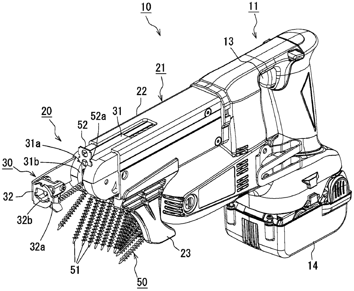
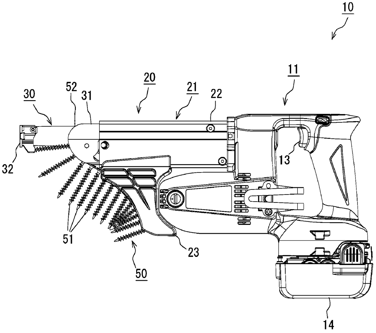
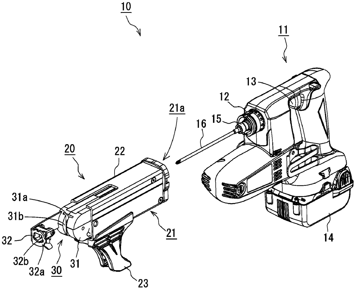
[0085] The screwdriver 10 for connecting screws according to this embodiment uses a connecting screw 50 in which a plurality of screws 51 are connected by a connecting band 52 . Such as Figure 1~3 As shown, the screwdriver 10 includes a tool body 11 and a fastener supply device 20 attached to the tool body 11 . A mounting portion 12 is provided at the front end of the tool body 11 , and the connecting portion 21 a at the rear end of the fastener supply device 20 can be fitted outside the mounting portion 12 , whereby the fastener supply device 20 can be detached from the tool body 11 .

[0086] Such as image 3 As shown, the tool main body 11 includes a bit mounting portion 15 at a front end portion covered by the fastener supply device 20 , and a screwdriver bit 16 is mounted on the bit mounting portion 15 . When the trigger 13 of the tool main body 11 is pulled, a motor (not s...


PUM


Abstract

A screw feeding mechanism of a screw driver (10) is provided. The screw feeding mechanism includes a base part (31) and a nose part (30) slidably provided on the base part (31). The nose part (30) includes a rotatable wheel member (33) and an arm member (37) connected to the wheel member (33). The base part (31) includes a guide member (24) having a guide portion (24a) configured to guide a movement of the arm member (37) when the nose part (30) slides. A sliding of the nose part (30) causes a screw feeding operation, and a further sliding of the nose part (30) causes a screw driving operation. The arm member (37) is configured and arranged to vibrate or to rotate in conjunction with at least one of the screw feeding operation and the screw driving operation.

Description

technical field [0001] The invention relates to a screw driving machine and a screw conveying mechanism for sequentially transporting connecting screws formed by connecting a plurality of screws with a connecting belt to a driving position. Background technique [0002] According to the screwdriver for connecting screws disclosed in JP2006-305671A, the head is pushed in by pressing the head to the workpiece to be driven, and the feeding operation of the connecting screw and the driving of the connecting screw are performed in conjunction with this action. action. Specifically, the arm swings in conjunction with the operation of pressing the nose, and the wheel is rotated by the swing of the arm to feed out the screws one by one. When the machine head is further pressed in, the sent screw is pressed out by the bit, and the screw is tightened by the bit driven by rotation to drive into the driven part. When the driving action is finished, the machine head returns to the stan...

Claims


Application Information

Patent Timeline
Patent Type & Authority Patents(China)
IPC IPC(8): B23P19/06
CPCB25B23/045
Inventor 山本博纪野田口洋成
Owner MAX CO LTD
Features
  • R&D
  • Intellectual Property
  • Life Sciences
  • Materials
  • Tech Scout
  • Unparalleled Data Quality
  • Higher Quality Content
  • 60% Fewer Hallucinations
Learn More