Rheostat Structure of Electrohydraulic Rheostat Starter

A starter and electro-hydraulic technology, applied in the direction of liquid resistors, starter parts, etc., can solve the problems of large waste of electric energy and low efficiency of high current, and achieve the effects of extended maintenance cycle, reasonable structure and low cost

Active Publication Date: 2017-08-15
南通曼淇威电气有限公司
View PDF5 Cites 1 Cited by
  • Summary
  • Abstract
  • Description
  • Claims
  • Application Information

AI Technical Summary

Problems solved by technology

[0002] The electro-hydraulic rheostat starter is used to start the motor. We know that when the motor starts, the starting current is very large. At this time, the efficiency of the large current is very low. Therefore, the waste of electric energy is very large. In order to solve this technical problem, a common solution One is to connect rheostats in series to limit the current, gradually increase the speed of the motor through the rheostats, and finally achieve the goal of saving energy. variable resistance

Method used


Image

  • Rheostat Structure of Electrohydraulic Rheostat Starter
  • Rheostat Structure of Electrohydraulic Rheostat Starter
  • Rheostat Structure of Electrohydraulic Rheostat Starter

Examples


Embodiment Construction

[0037] Now in conjunction with accompanying drawing, the present invention will be further described:

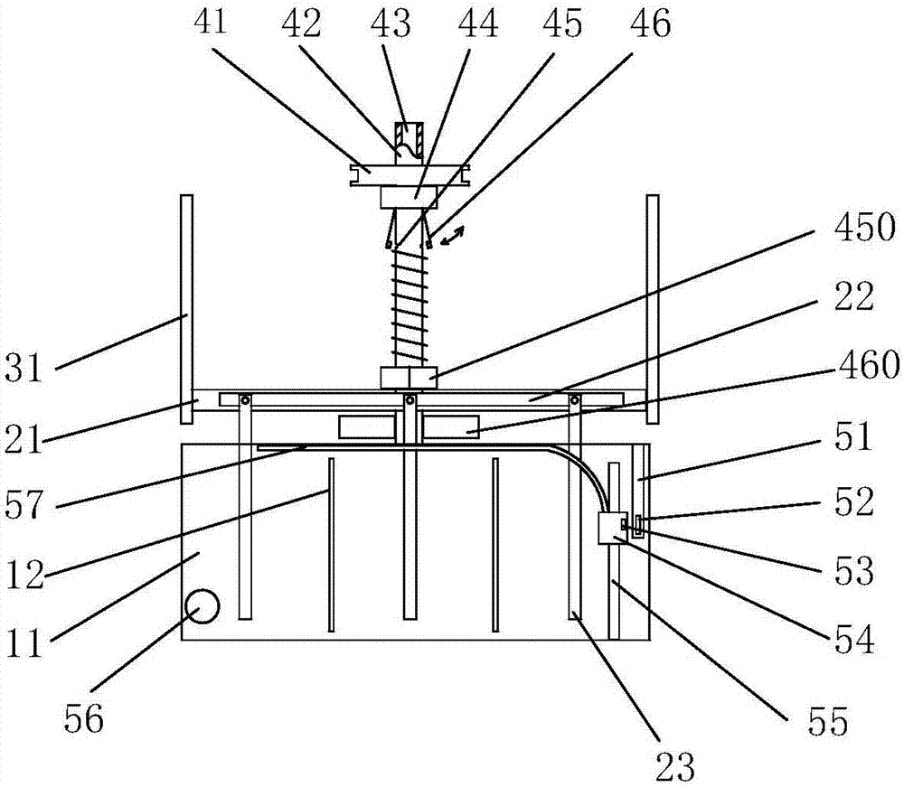
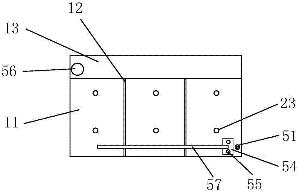
[0038] As shown in the figure, the water tank 11 is used as a water resistance;

[0039] Three pairs of electrode rods 23 are connected to water resistors and can output three resistance values;

[0040] The electrode rod lifting structure can simultaneously control the movement of one of each pair of electrode rods 23, thereby changing the water resistance;

[0041] Also includes:

[0042] There are two positioning columns 55, which are fixed in the water tank 11;

[0043] The buoy 54 is sleeved on the positioning column 55 and can move up and down with the water level;

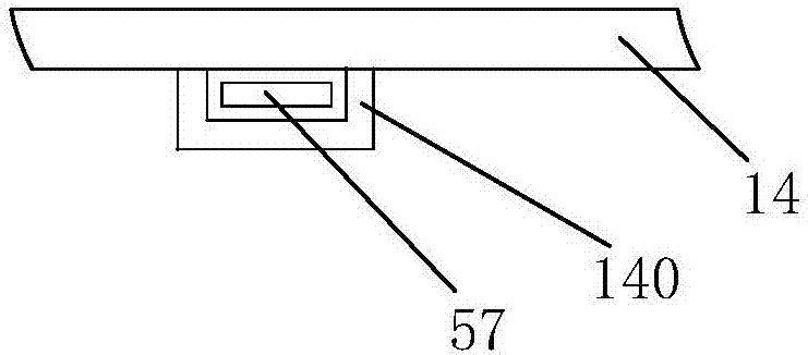
[0044] Flexible indicating strip 57, the slot 140 of partly inserting water tank cover 14 inner surfaces, an end point and buoy 54 are fixed, along with buoy 54 moves up and down, can convert the vertical change of water level into horizontal change by flexible indicating strip 57.

[0045] The water t...


PUM


Abstract

The invention discloses a rheostat structure of an electrical-hydraulic rheostat starter. The rheostat structure comprises a water tank, three pairs of electrode bars and an electrode bar lifting structure. The rheostat structure further comprises two locating columns, a buoy and a flexible indication strip, wherein the locating columns are fixed into the water tank; the buoy is arranged on one locating column in a sleeving mode and can move vertically along with the water level; the flexible indication strip is partly inserted in a slot formed in the inner surface of a water tank cover, one end of the flexible indication strip is fixed to the buoy, the flexible indication strip moves vertically along with the buoy, and vertical change of the water level can be converted into horizontal change through the flexible indication strip. The water tank cover is provided with holes which the electrode bars are inserted in, seal rings arranged outside the electrode bars in a sleeving mode and a housing used for fixing the seal rings to the inner surface of the water tank cover. The rheostat structure further comprises a standby water tank, wherein the standby water tank is adjacent to the water tank, a water pump is arranged in the standby water tank, and the water pump can inject water in the standby water tank into the water tank through an inlet in the upper portion of the water tank. The rheostat structure further comprises a magnetic material and a reed switch which are used for controlling the water pump to work. The rheostat structure of the electrical-hydraulic rheostat starter has the advantages of being reasonable in structure, low in cost, easy and convenient to maintain and longer in maintenance period.

Description

technical field [0001] The invention relates to a rheostat structure of an electro-hydraulic rheostat starter, which belongs to the field of motor soft starting. Background technique [0002] The electro-hydraulic rheostat starter is used to start the motor. We know that when the motor starts, the starting current is very large. At this time, the efficiency of the large current is very low. Therefore, the waste of electric energy is very large. In order to solve this technical problem, a common solution One is to connect rheostats in series to limit the current, gradually increase the speed of the motor through the rheostats, and finally achieve the goal of energy saving. variable resistance. In the prior art, in order to avoid factors such as water leakage and electricity leakage, no water level indication is provided, and when the water level drops, water is added temporarily. Contents of the invention [0003] Based on the above deficiencies, the present invention pro...

Claims


Application Information

Patent Timeline
Patent Type & Authority Patents(China)
IPC IPC(8): H02P1/02H01C10/02
CPCH01C10/02H02P1/02
Inventor 江永江加宝章春全
Owner 南通曼淇威电气有限公司
Why Eureka
Try Eureka