ventilation device

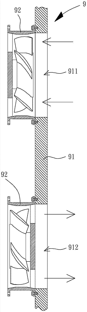
A technology for a ventilation device and a fan, which is applied to the components of a pumping device for elastic fluid, a non-variable-capacity pump, a machine/engine, etc., can solve the problem of reducing the service life, damage to the fan 92, and reducing the overall structure of the outer wall 91. strength, etc.

Inactive Publication Date: 2017-11-10
SUNONWEALTH ELECTRIC MACHINE IND
View PDF18 Cites 1 Cited by
  • Summary
  • Abstract
  • Description
  • Claims
  • Application Information

AI Technical Summary

Problems solved by technology

[0003] Yet this existing ventilating device 9 must offer at least two through-holes (being air inlet 911 and air outlet 912) on this outer wall 91 when actually installing and using, just can reach good circulating ventilation function; Therefore, easy Reduce the overall structural strength of the outer wall 91; moreover, when the outer wall 91 is provided with two through holes at the same time, the two air outlets will occupy too much area on the inner and outer surfaces of the outer wall 91, so the relative It is easy to cause the usable area of ​​the outer wall 91 to be greatly reduced; moreover, one side surface of the fan 92 is exposed to the outer wall 91, which is easy to cause damage to the fan 92 after being exposed to the sun or rain, thereby reducing its service life.

Method used


Image

  • ventilation device
  • ventilation device
  • ventilation device

Examples


Embodiment Construction

[0036] In order to make the above and other objects, features and advantages of the present invention more comprehensible, preferred embodiments of the present invention will be described in detail below together with the accompanying drawings.

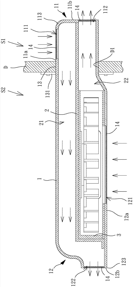
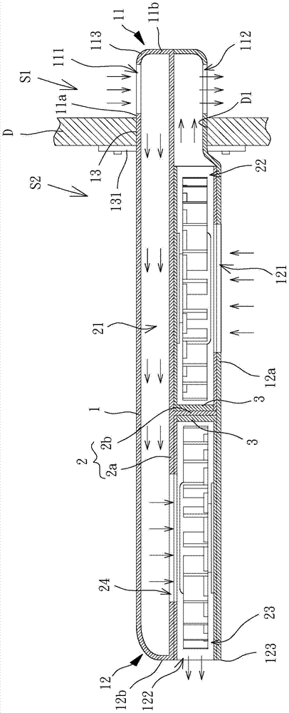
[0037] Please refer to figure 2 As shown, it discloses a combined sectional view of the ventilation device according to the first preferred embodiment of the present invention. The ventilation device is used to be installed on a partition D. One side of the partition D is the external space S1, and the opposite side is Inner space S2; wherein the ventilation device at least includes an air guide housing 1, a partition 2 and at least one fan 3, the air guide housing 1 is installed in a through hole D1 separately opened in the partition D, the partition The component 2 and the at least one fan 3 are arranged inside the air guide housing 1 .

[0038] The wind guide housing 1 has a first end 11 and a second end 12 opposite to each other...


PUM


Abstract

The invention discloses a ventilation device which is arranged on an isolation piece. The ventilation device comprises an air guide shell, a separator and at least one fan, wherein the air guide shell is provided with a first air inlet, a first air outlet, a second air inlet and a second air outlet; the separator is arranged in the air guide shell and is used for separating the interior of the air guide shell into a plurality of flow guide spaces; the fan is combined with the air guide shell and is used for leading in and leading out air flow. Therefore the separator can be matched with the ventilation device to supply a good circulating ventilation function by being only provided with a single permeation hole.

Description

technical field [0001] The present invention relates to a ventilation device, in particular to a ventilation device capable of enabling the external space and the internal space to achieve the function of circulating ventilation. Background technique [0002] Please refer to figure 1 As shown, a kind of existing ventilation device 9 is disclosed, and the ventilation fan device 9 is generally installed on the outer wall of a building or the casing of an electronic product, etc., taking the outer wall 91 of a building as an example, generally speaking, the outer wall The outer side of the wall 91 is the external space, and the inner side of the outer wall 91 is the inner space, wherein the outer wall 91 must be provided with an air inlet 911 and an air outlet 912, and a fan 92 is respectively installed at the air inlet 911 and the air outlet 912 In this way, when the fan 92 is in operation, the external airflow can be introduced from the external space to the internal space t...

Claims


Application Information

Patent Timeline
Patent Type & Authority Patents(China)
IPC IPC(8): F04D29/54
CPCF04D29/541
Inventor 洪银树
Owner SUNONWEALTH ELECTRIC MACHINE IND
Why Eureka
Try Eureka