Electric heating element

An electric heating element, a heating element technology, applied in the direction of the shape of the heating element, etc., can solve the problems of increasing the outer diameter and the like

Inactive Publication Date: 2015-04-29
HOTSET HEIZPATRONEN & ZUBEHOR
View PDF6 Cites 2 Cited by
  • Summary
  • Abstract
  • Description
  • Claims
  • Application Information

AI Technical Summary

Problems solved by technology

These known solutions mainly lead to an increase in the

Method used


Image

  • Electric heating element
  • Electric heating element
  • Electric heating element

Examples


Embodiment Construction

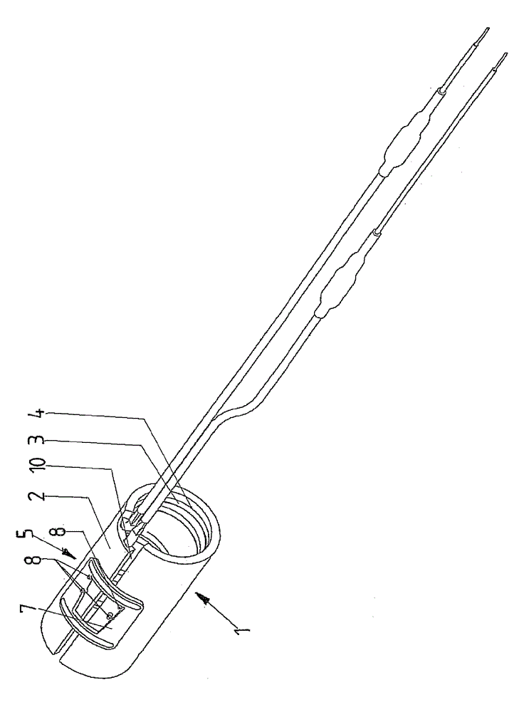
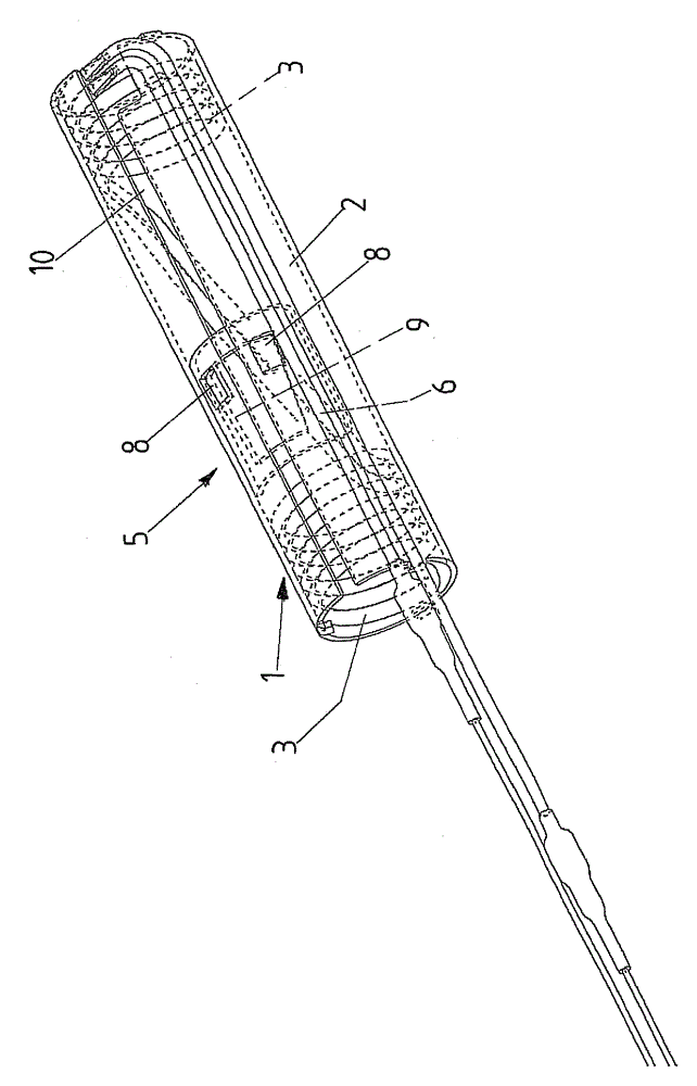
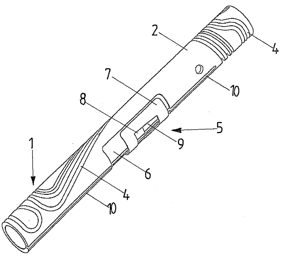
[0038] according to figure 1 The embodiment of FIG. 1 shows a heating element according to the invention having a heating body arranged externally on the shell of the respective heating body and an external wedge latch. Figure 7 and 8 An embodiment of a heating element is shown with a heating body arranged inside the housing and an external wedge-shaped latch. according to eg Figures 1 to 6 In the above-mentioned embodiment, the heating body is embedded in the material of the shell tube, and in accordance with Figure 11 and 12 The same is true in the embodiment of , but the heating body is arranged inside the shell, while the wedge-shaped latch is arranged outside. in accordance with Figure 5 and 6 In an embodiment, the heating body is embedded in the shell. in accordance with Figure 7 and8 with in accordance with Figure 9 and 10 In the embodiment, the heating body is installed on the inner side of the shell of the heating element, while the wedge-shaped latch ...


PUM


Abstract

The invention relates to an electric heating element (1) formed by a pipe (2) with a longitudinal slit, and provided with a bendable heating body (3). The heating body is installed on a housing layer; the pipe (2) can be clamped by a clamping device (5) to a to-be-heated body; a recessed pit (6) is formed in the housing layer of the heating body to form the clamping device (5); the recessed pit covers teh longitudinal slit (10); a sliding plate (7) is movably arranged in the recessed pit along the heating element (1); the bottom surface of the sliding plate opposite to the recessed pit (6) returns behind an alinging line of the housing layer; projections (8) inserted into window-shaped notches (9) are formed on two sides of the longitudinal slit (10) in the recessed pit (6); the projections are matched wtih longitudinal ridges of the notches (9), so the sliding plate (7) enables the heating body (1) to be fastened on the to-be-heated object.

Description

technical field [0001] The invention relates to an electric heating element for heating cylindrical or tubular objects, in particular for nozzles of plastic or metal casting equipment or injection molding equipment, wherein the heating element is composed of partially or completely longitudinally opened narrow slotted tubes, or shell plates bent into a tubular shape forming or having partial or entire longitudinal slits, or composed of a plurality of bent shell plates assembled into a tubular shape, the heating element has at least one bendable An electric heating body having a shell and at least one heat conductor arranged insulatively in an insulating material filling of the shell, wherein the heating body is mounted on the shell of the tube or is preferably inserted or pressed into Into the receiving groove on the shell of the tube or the shell plate, wherein the tube or the shell plate bent into a tubular shape can be clamped relative to the object to be heated by means of...

Claims


Application Information

Patent Timeline
IPC IPC(8): H05B3/40B29C33/02B22D17/20
CPCH05B3/40B22D17/2038B29C45/2737B29C2045/2743
Inventor B. 西贝格
Owner HOTSET HEIZPATRONEN & ZUBEHOR
Why Eureka
Try Eureka