Power drawer device with stopper

A technology of drawer cabinets and limit blocks, which is applied in the direction of switchgear, pull-out switch cabinets, electrical components, etc., which can solve problems such as inconvenient use, complex mechanical and electronic structures, and unfavorable maintenance of electrical cabinets, and achieve stable and balanced force , meet the requirements of stability and reliability, simple and reliable operation

Inactive Publication Date: 2015-08-12
STATE GRID CORP OF CHINA +1
View PDF9 Cites 1 Cited by
  • Summary
  • Abstract
  • Description
  • Claims
  • Application Information

AI Technical Summary

Problems solved by technology

[0002] The drawer device of the existing electrical appliance cabinet often needs to be manually pulled out, which causes inconvenience to use
However, the use of power to realize the pulling movement can not flexibly realize the releasable manual removal of the drawer assembly, thus causing disadvantages to the maintenance work of the electrical cabinet.
However, if you want to realize this kind of method that can not only push and pull by power, but also facilitate the manual removal of the drawer for maintenance, you need a more complicated mechanical and electronic structure, which will have a negative impact on maintenance and equipment costs.

Method used


Image

  • Power drawer device with stopper
  • Power drawer device with stopper

Examples


Embodiment Construction

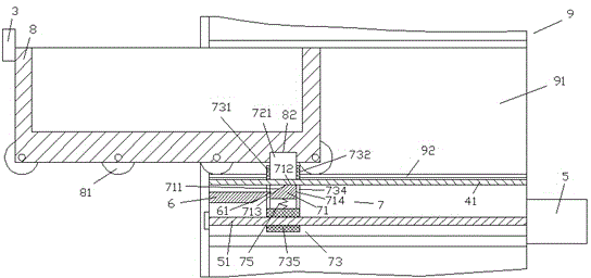
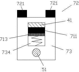
[0008] Combine below Figure 1-2 The present invention will be described in detail.

[0009] refer to Figure 1-2 According to an embodiment, a power drawer device with a limit block includes a frame body 9 and a drawer assembly 8, and rollers 81 are provided on both sides of the lower part of the drawer assembly 8 to accommodate the frame body 9. The horizontal guide rail 92 on the lower side of the accommodating cavity 91 of the drawer assembly 8 cooperates to allow the drawer assembly 8 to enter and exit the accommodating cavity 91 , the upper left side of the drawer assembly 8 is provided with a limit block 3 , and the frame 9 In the lower side of the transverse guide rail 92, a transverse slat 41 is fixedly arranged, and the transverse slat 41 carries a drive slider assembly 7, and the drive slider assembly 7 includes two support arm plates arranged left and right. 731, 732 and the U-shaped frame 73 formed by the bottom wall 735 fixedly connected between the two support...


PUM


Abstract

A power drawer device with a stopper comprises a frame (9) and a drawer assembly (8); two lower sides of the drawer assembly (8) are provided with rollers (81); the rollers are matched with transverse guide rails (92), arranged below a contain cavity (91) used for containing the drawer assembly (8) on the frame (9), so as to allow the drawer assembly (8) to enter / exit the contain cavity (91); the left upper side of the drawer assembly (8) is provided with the stopper (3); transverse battens (41) are fixed below the transverse guide rails (92) in the frame (9), and provided with a driving slide piece assembly (7) comprising two support arm plates (731, 732) arranged on the left and right.

Description

technical field [0001] The application relates to the field of electric power, in particular to an electric drawer device with a limit block. Background technique [0002] The drawer device of the existing electric appliance cabinet often needs to be manually pulled out, which causes inconvenience to use. However, the use of power to realize the pulling movement cannot flexibly realize the releasable manual removal of the drawer assembly, thereby causing disadvantages to the maintenance work of the electrical cabinet. However, if it is desired to realize such a method that can not only push and pull by power, but also facilitate manual removal of the drawer for maintenance, a more complex mechanical and electronic structure is required, which will have a negative impact on maintenance and equipment costs. Contents of the invention [0003] The object of the present invention is to provide an electric drawer device with a limit block, which can overcome the above-mentioned...

Claims


Application Information

Patent Timeline
IPC IPC(8): H02B11/173
CPCH02B11/173
Inventor 楼碧云
Owner STATE GRID CORP OF CHINA
Why Eureka
Try Eureka