Gantry type large-diameter paper dividing and cutting machine

A gantry-type, large-diameter technology, applied in the direction of winding strips, sending objects, thin material processing, etc., can solve the problems of low winding efficiency, poor paper surface protection, etc., and achieve the effect of simple structure and convenient use

Active Publication Date: 2015-09-09
NANJING JIA XU MACHINERY MFG
View PDF7 Cites 5 Cited by
  • Summary
  • Abstract
  • Description
  • Claims
  • Application Information

AI Technical Summary

Problems solved by technology

[0006] The purpose of the present invention is to provide a gantry-type large-diameter paper slitting machine, which solves the problem that in the prior art, the dust on the bottom surface of the paper is easy to absorb and the surface of the paper is not well protected. Post-slitting take-up shafts, which cause counting defects in the inefficiency of rewinding

Method used


Image

  • Gantry type large-diameter paper dividing and cutting machine
  • Gantry type large-diameter paper dividing and cutting machine
  • Gantry type large-diameter paper dividing and cutting machine

Examples


Embodiment 1

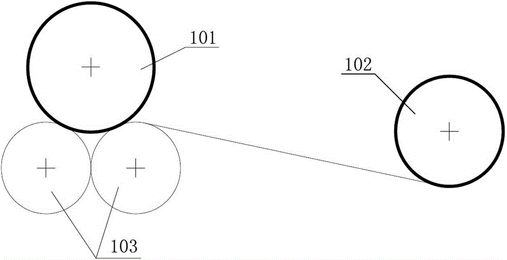
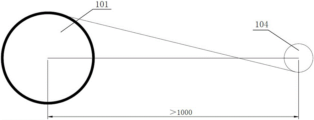
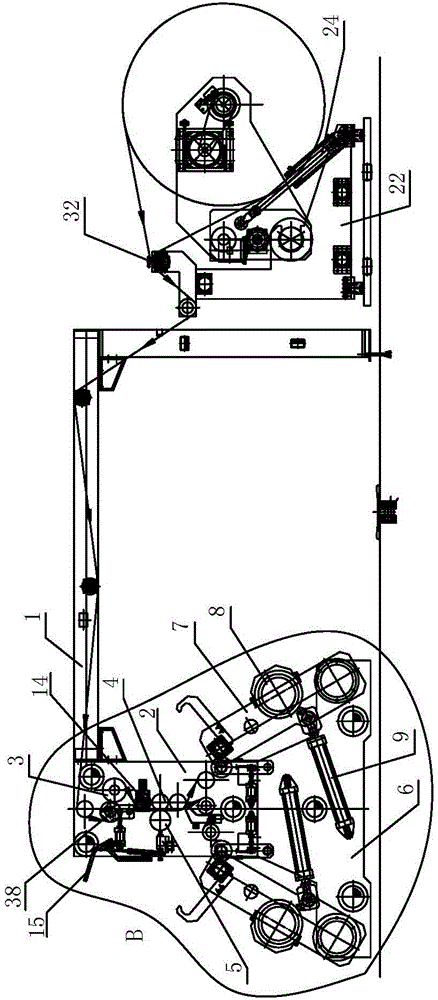
[0054] Such as image 3 and Figure 13 The gantry-type large-diameter paper slitting machine shown includes a gantry-type frame 1, a traction and slitting mechanism, an unwinding device arranged at one end of the gantry-type frame 1, and a traction and slitter arranged at the other end of the gantry-type frame 1. mechanism, a manual adjustment guide roller device 32, and N pressure-type winding devices arranged at the lower part of the traction and slitting mechanism, wherein N is an integer greater than or equal to 2, and the pressure-type winding devices are arranged along the width direction of the paper Distributed on both sides of the traction and slitting mechanism, the pressure-type winding devices on both sides of the traction and slitting mechanism are misplaced, and are respectively the inner pressure-type winding device on the side close to the unwinding device and the one far away from the unwinding device. One side of the external pressing type winding device, th...

Embodiment 2

[0064] The pressure type winding devices on both sides of the traction and slitting mechanism described in this embodiment share a winding shaft 10 respectively, as Figure 14 As shown, the two ends of the winding shaft 10 are the winding shaft swing arms 7 respectively (there are only two winding shaft swing arms 7 on each side of the traction and cutting mechanism in this embodiment). After the paper is cut, it is wound on two take-up shafts 10 respectively, and the paper 39 on the two take-up shafts is staggered and wound, and the distance between adjacent papers on the same take-up shaft 10 is the same as The width of the corresponding paper on the other winding shaft 10 is equal. Since the pressure-type winding devices on both sides of the traction and slitting mechanism in this embodiment share a take-up shaft 10 respectively, the length of the take-up shaft 10 is relatively large, and wider paper can be curled, and the width of the paper only needs to be adjusted. The ...


PUM


Abstract

The invention discloses a gantry type large-diameter paper dividing and cutting machine which comprises a gantry type rack, a traction dividing and cutting mechanism arranged at the other end of the gantry type rack, an unwinding device arranged at one end of the gantry type rack, and N pressing type winding devices arranged on the lower portion of the traction dividing and cutting mechanism, wherein N is an integer larger than or equal to 2. The pressing type winding devices are distributed on the two sides of the traction dividing and cutting mechanism in the width direction of paper, and the paper is wound on the pressing type winding devices on the two sides of the traction dividing and cutting mechanism in a staggered mode. The gantry type large-diameter paper dividing and cutting machine has the advantages that the technical defects that in the prior art, paper absorbs dust on the bottom face easily, the surface of the paper can not be well protected, the paper needs to be wound on the same winding shaft and then the winding shaft is cut after winding, and winding efficiency is low are overcome, the structure is simple, and use is convenient.

Description

technical field [0001] The invention relates to a gantry-type large-diameter paper slitting machine, which belongs to the field of paper-plastic slitting. Background technique [0002] Paper slitters are widely used in the field of paper-plastic slitting. There are mainly two types of existing paper slitting machines: [0003] The first is ground roll, such as figure 1 As shown (101 in the figure is the take-up shaft, 102 is the unwinding shaft, and 103 is the support roller), the lower part of the take-up shaft of this paper slitting machine is supported by two support rollers, and there is a line contact between the take-up shaft and the support rollers. , as the winding progresses, the sum of the diameters of the winding paper on the winding shaft increases, and the weight also increases. Surface crushing, which causes damage to the surface of the paper. [0004] The second type of fixed shaft winding, such as figure 2 As shown (101 in the figure is the take-up shaft...

Claims


Application Information

Patent Timeline
Patent Type & Authority Applications(China)
IPC IPC(8): B65H35/02B65H19/30
CPCB65H19/30B65H35/02B65H2301/41445B65H2601/25
Inventor 沈江海冯小金
Owner NANJING JIA XU MACHINERY MFG
Why Eureka
Try Eureka