Wire fixing clamp

A wire fixing and wire clip technology, used in cable installation, overhead installation, electrical components, etc., can solve the problems of easy loosening, potential safety hazards, time-consuming and labor-intensive fixing of wires and insulators, etc. The effect of increasing the working time and enhancing the reliability of the power supply

Inactive Publication Date: 2015-10-14
STATE GRID CORP OF CHINA +1
View PDF0 Cites 2 Cited by
  • Summary
  • Abstract
  • Description
  • Claims
  • Application Information

AI Technical Summary

Problems solved by technology

[0004] The technical problem to be solved by the present invention is that the existing way of fixing wires and insulators is time-consuming, labor-intensive, easy to loosen, and has potential safety hazards

Method used


Image

  • Wire fixing clamp
  • Wire fixing clamp
  • Wire fixing clamp

Examples


Embodiment Construction

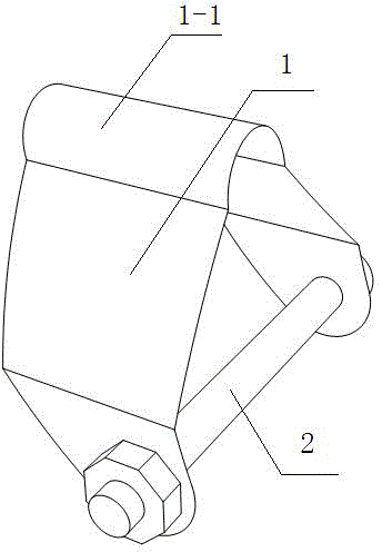
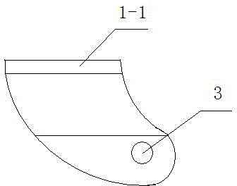
[0014] Such as Figure 1-3 As shown, the present invention includes a clamp body 1 and a fixing member 2. The clamp body 1 includes a clamping groove 1-1 for clamping wires, and fixed wings on both sides of the clamping groove 1-1. Set connection hole 3.

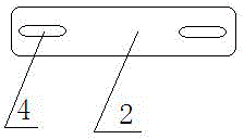
[0015] The fixing member can also be a fixing card, and a screw hole 4 is respectively provided at both ends of the fixing card, and the screw hole 4 is used for correspondingly connecting the connecting holes 3 on the two fixing wings.

[0016] The fixing member may be a screw rod and a nut, and the screw rod penetrates through the two connection holes 3 and is then rotatably connected and fixed with the nut. When the fixing part of this kind of structure is adopted, it is more convenient to adjust, and the nut can be loosened to be installed, and the nut can be tightened to be fixed.

[0017] During use, a product of the present invention is respectively arranged at both ends of the wire to be fixed, and the fixing parts...


PUM


Abstract

The invention discloses a wire fixing clamp comprising a clamp body and a fixer. The clamp body comprises a clamping groove for clamping a wire and fixing wings on both sides of the clamping groove. The fixing wings are provided with connecting holes. Both ends of the fixer are connected with the connecting holes of the two fixing wings, respectively. The wire fixing clamp is easy to install and simple in structure. The use of the wire fixing clamp substitutes for a conventional metallic line binding manner. A wire is fixed to an insulator through bolted connection on the wire fixing clamp and a defect caused by the metallic line binding manner is prevented.

Description

technical field [0001] The invention relates to a wire fixing clamp, which is used for fixing wires of power distribution overhead lines on insulators. Background technique [0002] In the prior art, the erection of overhead distribution lines adopts the combination of reinforced concrete poles, cross arms, fittings and other components, and insulators are used to support and fix the wires at the top of the cement poles. For straight poles, the insulators under normal working conditions Bear the vertical load of the conductor and the wind load on the side of the line. [0003] At present, the fixed connection of overhead conductors on pin insulators is fixed by winding and fixing single-core metal wires, and binding wire winding methods such as top slot binding and neck slot binding are generally used. The winding process stipulated in the regulations is used by the construction personnel to work at high altitude on the pole tower. The process is relatively complicated, the...

Claims


Application Information

Patent Timeline
Patent Type & Authority Applications(China)
IPC IPC(8): H02G7/00
CPCH02G7/053
Inventor 史晓鹤王晓峰
Owner STATE GRID CORP OF CHINA
Why Eureka
Try Eureka