

Hydraulic system of oiling machine
A technology of hydraulic system and oil dispenser, which is applied in the directions of liquid distribution, conveying or transfer device, special distribution device, packaging, etc. It can solve the problems of inconvenient installation and maintenance, affecting the work of hydraulic system, low oil absorption capacity of pump, etc. The effect of pipeline distribution, safety and reliability improvement, and reliability assurance
- Summary
- Abstract
- Description
- Claims
- Application Information
AI Technical Summary
Problems solved by technology
Method used
Image

Examples
Embodiment Construction
[0026] For the convenience of those skilled in the art to understand, the present invention will be further described in detail below in conjunction with the accompanying drawings and embodiments.
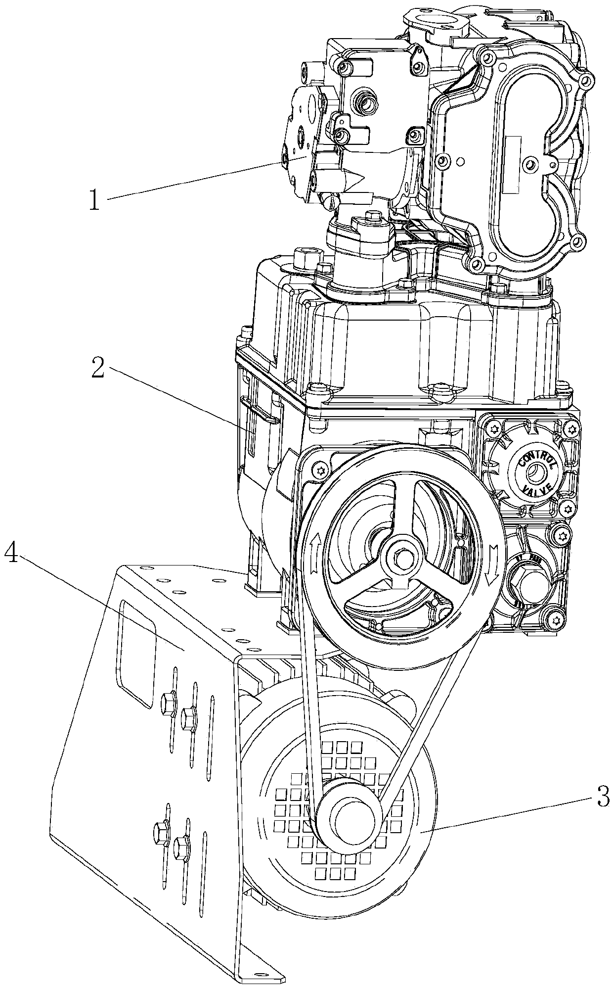
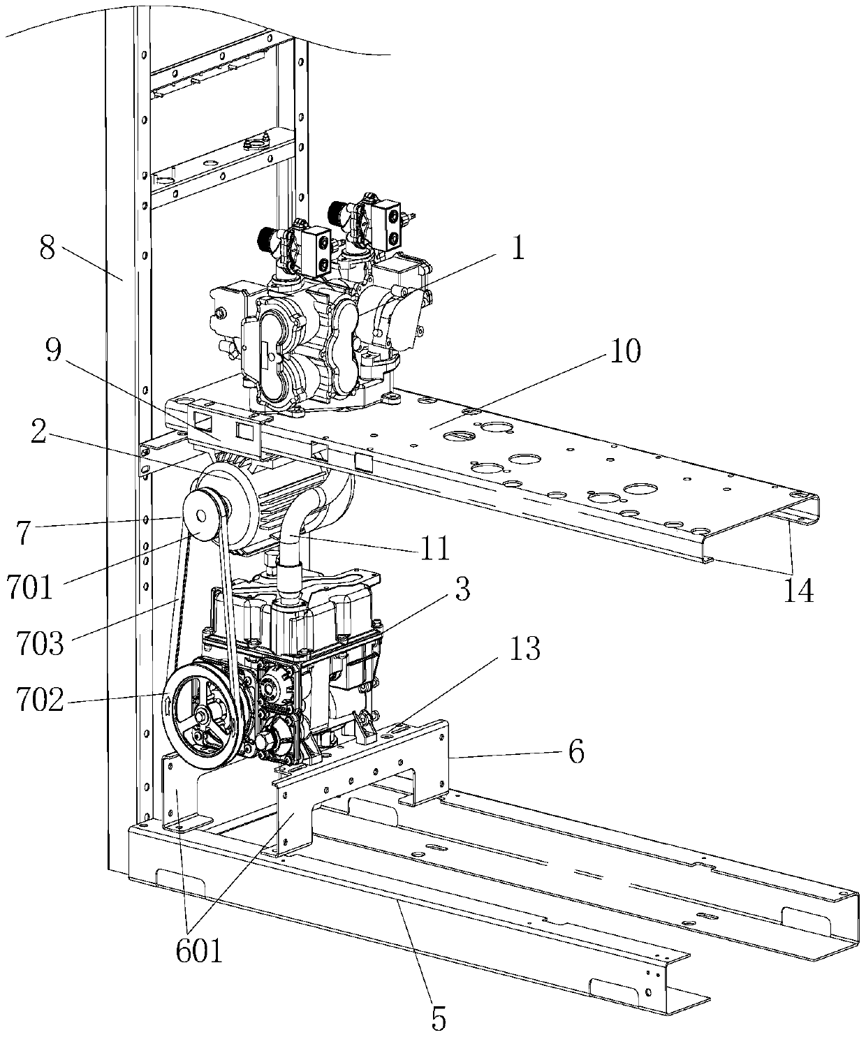
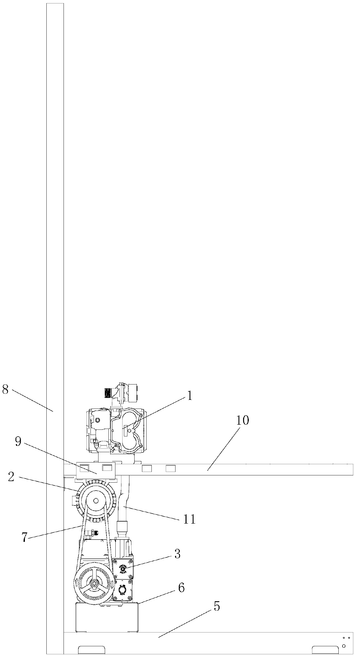
[0027] Such as figure 2 and image 3 As shown, the hydraulic system of the fuel dispenser includes a flowmeter 1, a motor 2, a pump 3, a support frame 5 and a base 6, the flowmeter 1 is connected to the pump 3, and the motor 2 is connected to the pump 3 through a transmission mechanism 7. The pump 3 is installed on the base 6 through the support frame 5; it also includes a column 8, a connecting frame 9, a support plate 10 and an oil outlet pipe 11, and the oil outlet pipe 11 is made of aluminum pipe. The lower end of the column 8 is fixed on the base 6, one end of the support plate 10 is fixed on the side wall of the column 8, the motor 2 is installed under the support plate 10 through the connecting frame 9, and the flowmeter 1 is installed on the support plate 10, the pump 3 ...
PUM
 Abstract
Description
Claims
Application Information