An earthing switch guiding arc striking angle

A technology of grounding switch and arc striking angle, which is applied in the direction of electric switches, electrical components, circuits, etc., can solve the problems of grounding switch blades fitting into the grounding static contact offset, unsafe on-site operation, and grounding switch burnout, etc., to achieve Reduce closing discharge, avoid arc discharge burning contact phenomenon, increase the effect of guiding arc strike angle

Active Publication Date: 2017-10-31
CHINA XD ELECTRIC CO LTD
View PDF5 Cites 0 Cited by
  • Summary
  • Abstract
  • Description
  • Claims
  • Application Information

AI Technical Summary

Problems solved by technology

[0003] The single-column vertical open grounding switch or the grounding switch attached to the isolating switch adopts a straight pole vertical opening structure. It is widely used because of its simple structure, few transmission links, and reliable operation. The grounding knife rod is long and the transmission distance is long. When the grounding switch is closed, it is easy to cause the grounding knife to deviate when it is connected to the grounding static contact due to the influence of wind force or transmission gap, so that the closing is not in place.
Sometimes there is a rebound phenomenon after closing, and the rebound will cause a false connection between the grounding knife and the grounding static contact, resulting in arc discharge. In severe cases, it will cause burning damage to the grounding switch, and also cause unsafe factors in the on-site operation.

Method used


Image

  • An earthing switch guiding arc striking angle
  • An earthing switch guiding arc striking angle
  • An earthing switch guiding arc striking angle

Examples


Embodiment Construction

[0023] The present invention will be further described in detail below in conjunction with the accompanying drawings, which are explanations rather than limitations of the present invention.

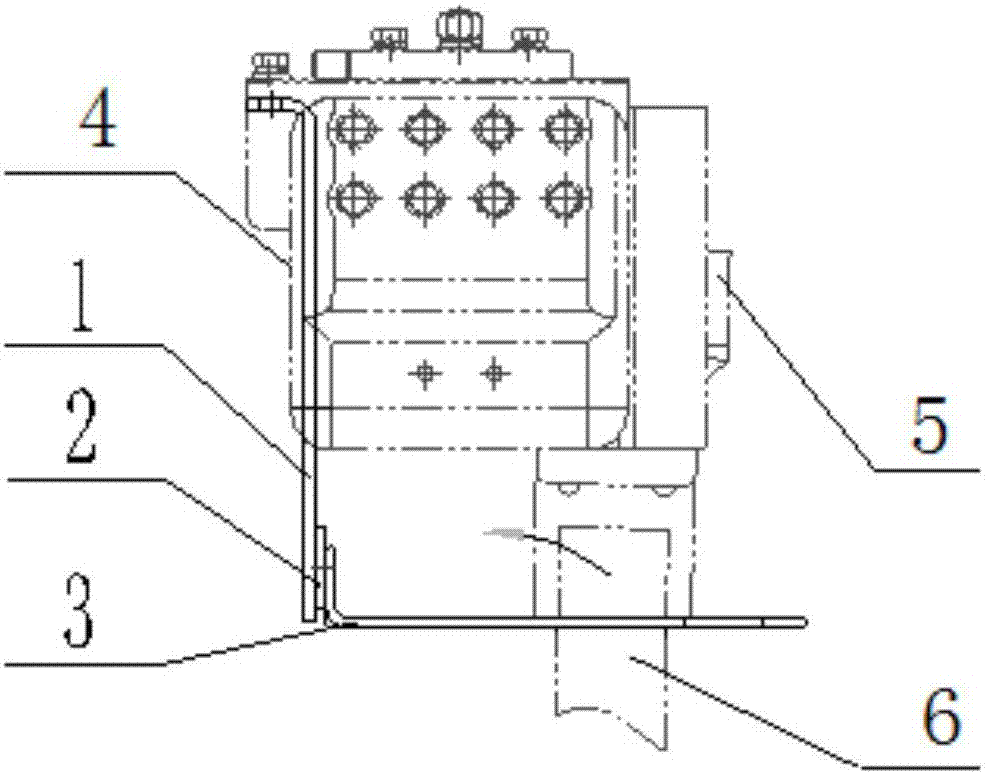
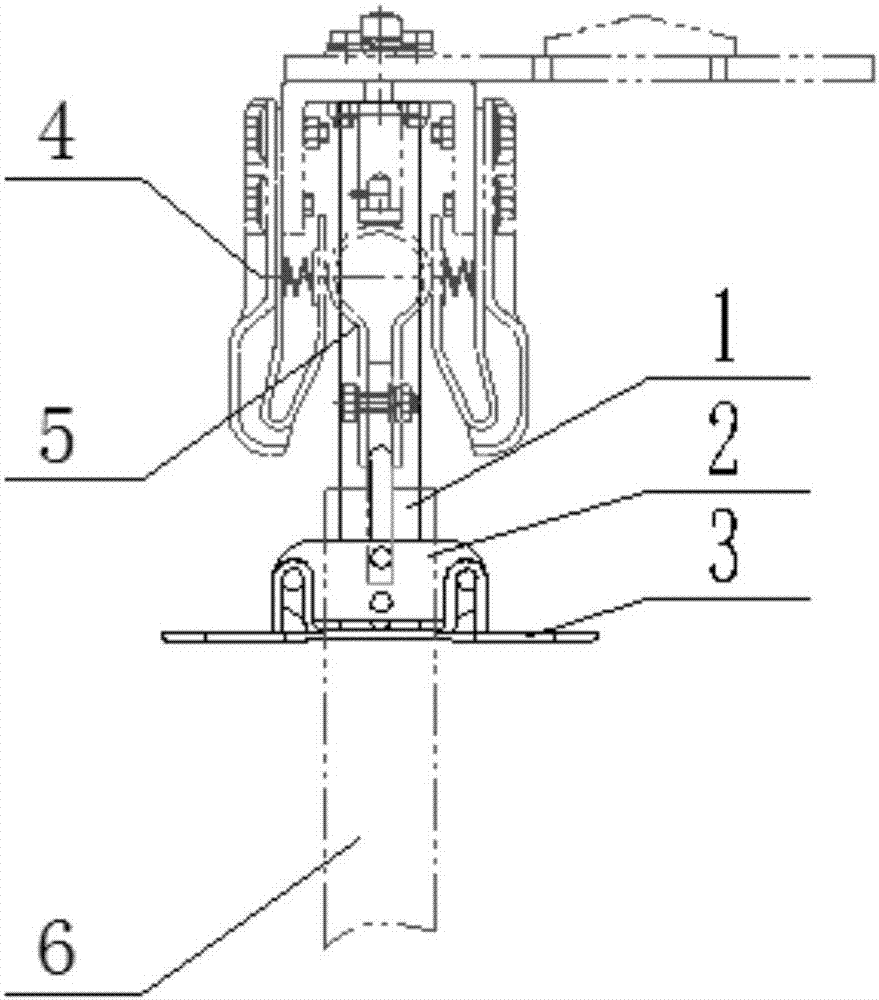
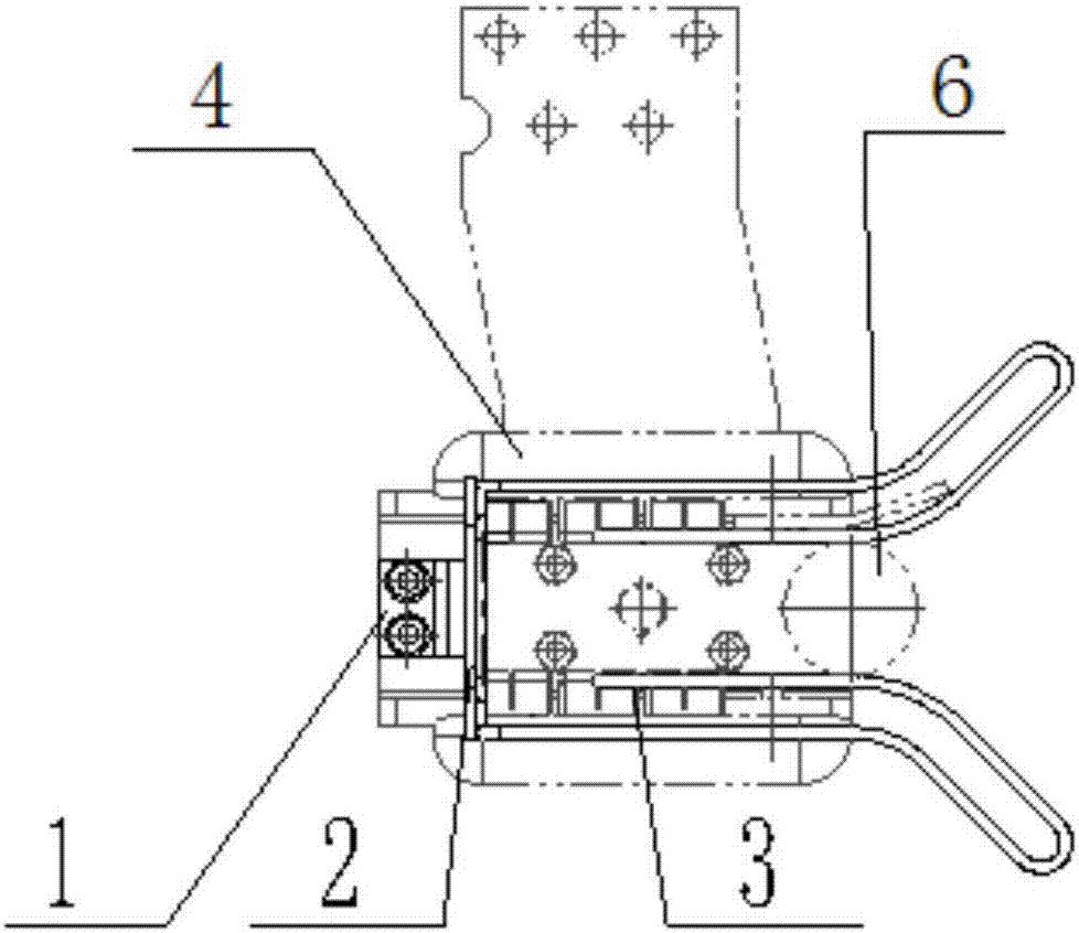
[0024] A grounding switch guide arc striking angle of the present invention, such as Figure 2a As shown, it includes limit bending plate 1, arc angle mounting plate 2 and guiding arc striking angle 3. The limit bending plate 1 is installed on the grounding static contact 4, and a long hole is processed on the limit bending plate 1. The limit bending plate 1 and the arc angle mounting plate 2 are connected by bolts installed on the long hole to fix the arc. The position of the corner mounting plate 2 is convenient for adjusting the installation height. The guide arc angle 3 is L-shaped, and the two side-by-side U-shaped structures that bend themselves on the vertical plane are fixed on the arc angle mounting plate 2 by screws. The shape guarantees the guidance of the grounding knife tu...


PUM


Abstract

The invention discloses a guiding arc-striking angle for a grounding switch. The guiding arc-striking angle comprises a limiting bent plate, an arc angle mounting plate and the guiding arc-striking angle, wherein the limiting bent angle is mounted at the back end of a grounding static contact; the plate surface of the limiting bent plate is used for limiting the movement destination position of a grounding movable contact; the arc angle mounting plate is fixedly connected with the limiting bent plate; the guiding arc-striking angle is arranged in an L-shaped manner; the perpendicular surface of the guiding arc-striking angle is fixed on the arc angle mounting plate while a guiding slot opening is formed in the horizontal surface of the guiding arc-striking angle; the guiding slot opening comprises a slot body and an inverted v-shaped opening formed in the outer end; the slot body is gradually contracted from outside to inside gradually; and when the grounding switch is switched on, a grounding knife switch tube is constantly in contact with the slot body. By adoption of the limiting plate, the movement destination position of the grounding movable contact is effectively limited; the guiding arc-striking angle is convenient to mount and reliable to fix due to the L-shaped arc angle mounting plate; the high-low positions of the guiding arc-striking angle can be adjusted, so that the guiding arc-striking angle is convenient to assemble and adjust; due to the inverted v-shaped opening of the guiding arc-striking angle, the guiding range is expanded; and the constant contact between the guiding arc-striking angle and a conductive tube of the grounding switch can be ensured by the elasticity of the guiding arc-striking angle after the guiding arc-striking angle is bent so as to avoid bounce of the switch-on state.

Description

technical field [0001] The invention relates to the design field of a high-voltage isolating switch and a grounding switch, in particular to a grounding switch guiding arc striking angle. Background technique [0002] With the rapid development of my country's economy and society, people's demand for electricity has also increased sharply. The scale of power grid and power generation construction has continued to increase, and higher and better requirements have been put forward for power equipment. Isolation switches and grounding switches are used in power stations. The power equipment with the largest usage is also constantly developing towards simpler structure and higher reliability. [0003] The single-column vertical open grounding switch or the grounding switch attached to the isolating switch adopts a straight pole vertical opening structure. It is widely used because of its simple structure, few transmission links, and reliable operation. The grounding knife rod is...

Claims


Application Information

Patent Timeline
Patent Type & Authority Patents(China)
IPC IPC(8): H01H9/30
CPCH01H9/30
Inventor 冯艳孟忠袁忠明李睿
Owner CHINA XD ELECTRIC CO LTD
Why Eureka
Try Eureka