Machine tool clamping mechanism

A technology of clamping mechanism and machine tool, which is applied in the direction of clamping, metal processing machinery parts, support, etc., can solve the problems of easy deformation, short use mission, unstable and firm clamping, etc. The effect of service life

Inactive Publication Date: 2016-12-07
NINGBO JINKAI MASCH TOOL CO LTD
View PDF7 Cites 4 Cited by
  • Summary
  • Abstract
  • Description
  • Claims
  • Application Information

AI Technical Summary

Problems solved by technology

[0003] However, the existing clamping mechanisms of machine tools are complex in structure, unstable and firm in clamping, and inconvenient to operate, and the backing plates used in machine tools are mostly pure iron plates, which are easily deformed by extrusion, and the use mission is short

Method used


Image

  • Machine tool clamping mechanism
  • Machine tool clamping mechanism

Examples


Embodiment 1

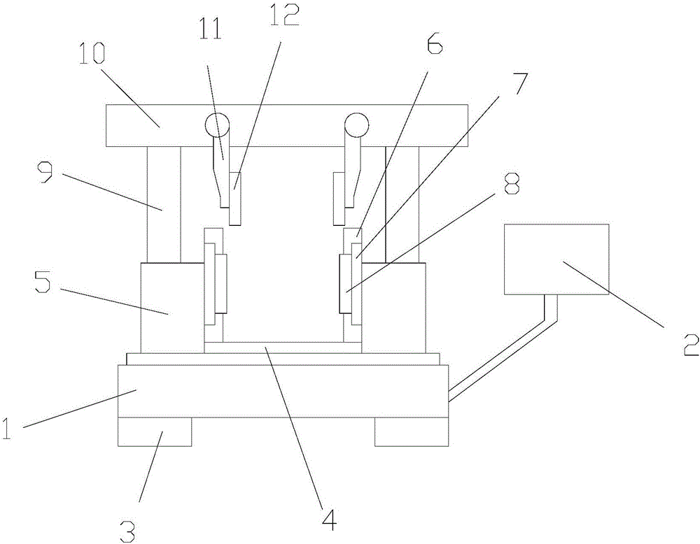
[0025] Such as figure 1 As shown, a clamping mechanism for a machine tool includes a machine base 1 and a controller 2, the bottom of the machine base 1 is provided with a pad 3, the pad 3 is fixed with the machine base 1, and the top of the machine base 1 The middle part is provided with a tray 4, and the tray 4 is fixed with the base 1, and the two sides above the base 1 are provided with an expander 5, and the expander 5 is fixed with the base 1, so that The inner side of the telescopic device 5 is provided with a clamping plate 6, a positioning plate 7 and a backing plate 8, the clamping plate 6 is located behind the positioning plate 7, the positioning plate 7 is fixed with the telescopic device 5, and the backing plate 8 is fixed in front of the positioning plate 7, and the telescopic rod 9 is arranged above the telescopic device 5, and the clamping beam 10 is arranged above the telescopic rod 9, and the clamping beam 10 is fixed with the telescopic rod 9, so that The c...

Embodiment 2

[0042] Such as figure 1 As shown, a clamping mechanism for a machine tool includes a machine base 1 and a controller 2, the bottom of the machine base 1 is provided with a pad 3, the pad 3 is fixed with the machine base 1, and the top of the machine base 1 The middle part is provided with a tray 4, and the tray 4 is fixed with the base 1, and the two sides above the base 1 are provided with an expander 5, and the expander 5 is fixed with the base 1, so that The inner side of the telescopic device 5 is provided with a clamping plate 6, a positioning plate 7 and a backing plate 8, the clamping plate 6 is located behind the positioning plate 7, the positioning plate 7 is fixed with the telescopic device 5, and the backing plate 8 is fixed in front of the positioning plate 7, and the telescopic rod 9 is arranged above the telescopic device 5, and the clamping beam 10 is arranged above the telescopic rod 9, and the clamping beam 10 is fixed with the telescopic rod 9, so that The c...

Embodiment 3

[0059] Such as figure 1 As shown, a clamping mechanism for a machine tool includes a machine base 1 and a controller 2, the bottom of the machine base 1 is provided with a pad 3, the pad 3 is fixed with the machine base 1, and the top of the machine base 1 The middle part is provided with a tray 4, and the tray 4 is fixed with the base 1, and the two sides above the base 1 are provided with an expander 5, and the expander 5 is fixed with the base 1, so that The inner side of the telescopic device 5 is provided with a clamping plate 6, a positioning plate 7 and a backing plate 8, the clamping plate 6 is located behind the positioning plate 7, the positioning plate 7 is fixed with the telescopic device 5, and the backing plate 8 is fixed in front of the positioning plate 7, and the telescopic rod 9 is arranged above the telescopic device 5, and the clamping beam 10 is arranged above the telescopic rod 9, and the clamping beam 10 is fixed with the telescopic rod 9, so that The c...


PUM


Abstract

The invention discloses a machine tool clamping mechanism. The machine tool clamping mechanism comprises a stand and a controller; a cushion block is arranged at the bottom of the stand, and is fixed with the stand; a tray is arranged at the middle part above the stand, and is fixed with the stand; extenders are arranged on two sides above the stand, and are fixed with the stand; clamping plates, positioning discs and cushion plates are arranged on the inner sides of the extenders; the clamping plates are positioned behind the positioning discs; the positioning discs are fixed with the extenders; the cushion plates are fixed in front of the positioning discs; the clamping plates are positioned behind the positioning discs; the positioning discs are fixed with the extenders; the cushion plates are fixed in front of the positioning discs; extension rods are arranged above the extenders; clamping cross beams are arranged above the extension rods, and are fixed with the extension rods; feeding mechanisms are arranged on the clamping cross beams, and are provided with wheels; and the controller is positioned on the right side of the stand. The machine tool clamping mechanism has the advantages of simple structure, stable clamping and convenience for operation; and the cushion plates are high in pressure and deformation resistance.

Description

technical field [0001] The invention relates to a clamping mechanism of a machine tool. Background technique [0002] In the machinery manufacturing industry, lathes are widely used to process various parts. When processing parts, the problem of clamping and positioning is involved. At present, when the existing clamps are working, one clamping surface is fixed, and then the other clamping surface is moved to achieve clamping. In this way, due to the one-way movement of a single clamping surface, especially in the frequent clamping and loosening process, it takes a lot of time, increases labor intensity, and reduces work efficiency. In view of the existing problems, it is necessary to design a mechanism for fast clamping of machine tool fixtures to shorten the moving time of the clamping surface, reduce labor intensity and improve work efficiency. [0003] However, the existing clamping mechanisms of machine tools are complex in structure, unstable and firm in clamping, an...

Claims


Application Information

Patent Timeline
Patent Type & Authority Applications(China)
IPC IPC(8): B23Q3/06B23Q3/10C22C33/04B23P15/00
CPCB23Q3/06B23P15/00B23Q3/101B23Q3/103C22C33/006C22C33/04
Inventor 肖双民吴杰锋王凯张卫卫胡泽睿
Owner NINGBO JINKAI MASCH TOOL CO LTD
Why Eureka
Try Eureka