
A traction-type metal wall-climbing robot
A wall-climbing robot and traction technology, applied in the field of robots, can solve the problems of small load capacity and poor obstacle-crossing ability, and achieve the effects of large load capacity, reliable adsorption and simple control.
- Summary
- Abstract
- Description
- Claims
- Application Information
AI Technical Summary
Problems solved by technology
Method used
Image

Examples
Embodiment Construction
[0022] Embodiments of the present invention will be further described below in conjunction with the accompanying drawings.
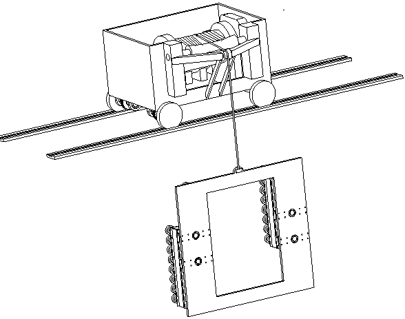
[0023] like Figure 1 to Figure 4 As shown, a traction-type metal wall-climbing robot includes a traction mechanism and a crawling mechanism, and the traction mechanism suspends the crawling mechanism on the metal wall through a traction rope.
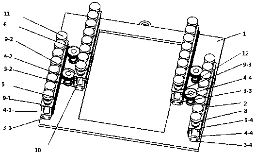
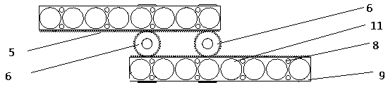
[0024] The crawling mechanism includes a frame 1, a fixed slider 2, a linear guide rail 3, a support frame 4, a rack 5, a gear 6, a linear motor 7, a support column 8, a support plate 9, a ball joint 10, an electromagnet 11, and a drive shaft 12. Eight fixed sliders 2 are installed on the left and right frames of the frame 1, and every two fixed sliders 2 form a group, and cooperate with a linear guide rail 3, so that the linear guide rail 3 can slide along the fixed slider 2 , the left and right frames of the frame 1 have two linear guide rails 3 installed in parallel; two transmission shafts 12 are installed b...
PUM
 Abstract
Description
Claims
Application Information