Guide Carriage with a Sensory Layer on the Raceway Insert

A rolling surface and sensing layer technology, applied in linear motion bearings, rotating parts that resist centrifugal force, bearings, etc., can solve problems such as reducing the measurement accuracy of sensors, and achieve the effect of simple manufacturing

Active Publication Date: 2017-12-15
ROBERT BOSCH GMBH
View PDF12 Cites 0 Cited by
  • Summary
  • Abstract
  • Description
  • Claims
  • Application Information

AI Technical Summary

Problems solved by technology

Since the sensor transmits only a small part of the total force to the guide carriage and thus measures this part, the measurement accuracy of the sensor with respect to the total force, which is exerted externally on all parts, is reduced. on the guide carriage

Method used


Image

  • Guide Carriage with a Sensory Layer on the Raceway Insert
  • Guide Carriage with a Sensory Layer on the Raceway Insert
  • Guide Carriage with a Sensory Layer on the Raceway Insert

Examples


Embodiment Construction

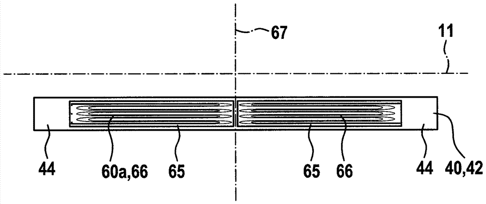
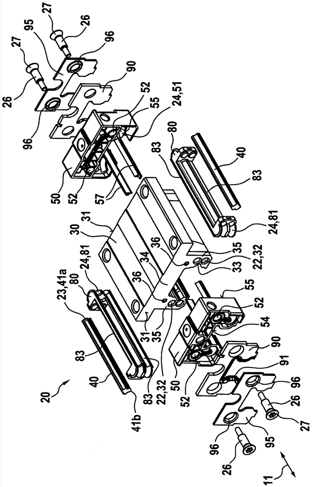
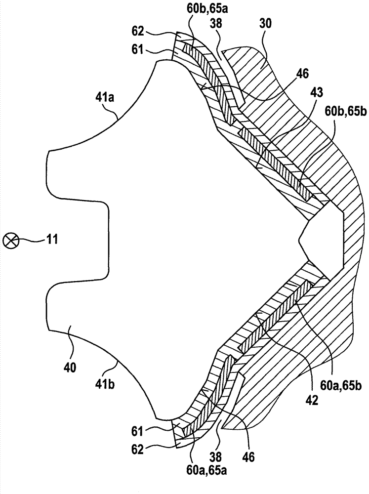
[0088] figure 1 An exploded view of the guide carriage 20 according to the invention is shown. Said guide carriage 20 comprises a body 30 made of non-hardened steel extending along the longitudinal axis 11 with a substantially constant U-shaped cross-section. V-shaped grooves 33 are respectively arranged on the inner sides of the U-legs 35 , against which grooves a separate running surface pad 40 , which is made of hardened rolling bearing steel, rests in each case. Two running surface pads 40 extend along the longitudinal axis 11 with a substantially constant cross section, wherein they each have two carriage running surfaces 41a, 41b, so that the guide carriage 20 has a total of four rows of spherical rolling bodies ( figure 2 Reference number 21 in ).

[0089] An end cap 50 with an inner longitudinal end face 55 is in direct contact with each of two opposite flat longitudinal end faces 31 of the main body 20 . The two end caps 50 are constructed identically, wherein the...


PUM


Abstract

A guide carriage for use with a guide rail includes a main body and a separate raceway insert. A first carriage raceway that extends parallel to a longitudinal axis is disposed on the raceway insert. The first carriage raceway is assigned a first lateral face, which is disposed on that side of the raceway insert that is opposite the first carriage raceway. The first carriage raceway is assigned a row of rolling bodies capable of being brought into rolling engagement with the first carriage raceway and an assigned first rail raceway on the guide rail. The raceway insert is supported in a force-transmitting manner on the main body by way of the first lateral face. The raceway insert has a sensory layer which in the direction of the longitudinal axis extends across at least 80% of the length of the raceway insert.

Description

technical field [0001] The invention relates to a guide carriage according to the preamble of claim 1 . Background technique [0002] DE 10 2008 051 682 A1 discloses a guide carriage which is a component of a linear rolling bearing which also includes a guide rail. The guide carriage has a main body and four rolling surface pads. A carriage raceway for roller-shaped rolling bodies, which are mounted in a force-transmitting manner between the guide rail and the guide carriage, is arranged on each raceway pad. A sensor is mounted between the rolling surface pad and the main body, the sensor being constructed in the form of a piezoelectric ceramic. The sensor is here received in a borehole of a metal plate, wherein the metal plate is mounted force-transmittingly between the rolling surface pad and the main body. The sensor is thus unloaded, so that there is no fear of breaking the piezoceramic. Since the sensor transmits only a small part of the total force to the guide car...

Claims


Application Information

Patent Timeline
Patent Type & Authority Applications(China)
IPC IPC(8): F16C29/04F16C29/06
CPCF16C29/04F16C29/06F16C29/0604F16C29/0645F16C33/61F16C41/00F16C2202/36F16C2233/00G01L5/0019
Inventor F.布吕姆C.扬森M.施托克
Owner ROBERT BOSCH GMBH
Why Eureka
Try Eureka