Flange workpiece clamping device

A clamping device and workpiece technology, which is applied to used abrasive processing devices, manufacturing tools, metal processing equipment, etc., can solve the problems of inconvenient replacement of workpieces, damage to workpieces, and low processing efficiency of workpieces, and saves the cost of loading and unloading workpieces. Time and practicality

Inactive Publication Date: 2018-01-23
成都源云机械有限公司
View PDF0 Cites 0 Cited by
  • Summary
  • Abstract
  • Description
  • Claims
  • Application Information

AI Technical Summary

Problems solved by technology

For example, when sandblasting a workpiece, it is necessary to fix the workpiece before it can be sandblasted. However, the effect of the existing clamps on the workpiece is not ideal. The clamping device will damage the surface of the workpiece, and the workpiece is easy to be pinched. Or scratches, affect the surface quality of the workpiece, and when changing parts, the disassembly and installation of the workpiece need to loosen or tighten multiple parts, causing inconvenience to replace the workpiece, making the processing efficiency of the workpiece low

Method used


Image

  • Flange workpiece clamping device

Examples


Embodiment Construction

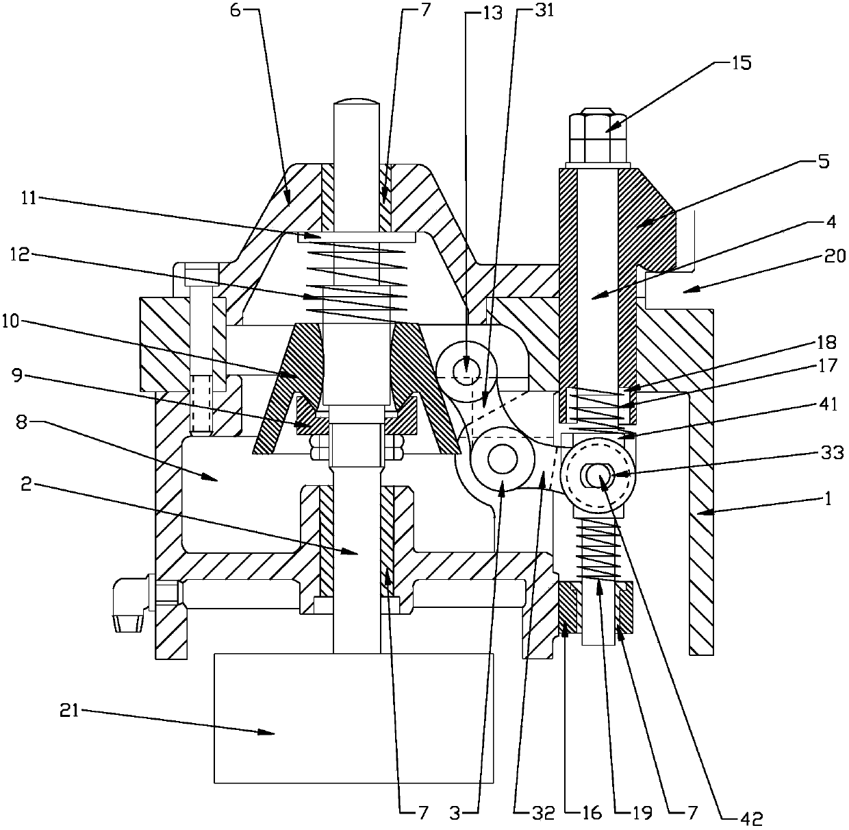
[0015] The present invention will be further described below in conjunction with the accompanying drawings.

[0016] like figure 1 As shown, the present invention provides a flange workpiece clamping device, including a base 1, a driving rod 2, a linkage rod 3, and a pressure rod 4, wherein the base 1 is provided with a cover 6, and the cover 6 is connected to the base The seat 1 is provided with a through hole, the axes of the two through holes are consistent, the through hole is provided with a shaft sleeve 7, the driving rod 2 is slidingly fitted with the shaft sleeve 7, the lower end of the driving rod 2 is connected with a cylinder 21, and the base 1 Combined with the cover body 6 to form a structure with a cavity 8, a fixed expansion block 9 is fixedly sleeved on the drive rod 2 located in the cavity 8, and a movable expansion block 10 is provided above the fixed expansion block 9, and the movable expansion block 10 There are end faces that abut against each other with ...


PUM


Abstract

The invention relates to the technical field of machining, in particular to a flange workpiece clamping device. The flange workpiece clamping device comprises a base, a drive rod, a linkage rod and apressing rod; the base is provided with a cover, the cover and the base are each provided with a through hole, and the axes of the two through holes are coincident; the drive rod is in sliding fit with the through holes, and a cylinder is connected to the lower end of the drive rod; the base and the cover are combined to form a structure with a cavity; the portion, in the cavity, of the drive rodis fixedly sleeved with a fixed expansion block; a movable expansion block is arranged above the fixed expansion block, end faces, abutting against each other, are arranged between the movable expansion block and the fixed expansion block, and the movable expansion block is in sliding fit with the drive rod in the axial direction; and a first compression spring is arranged between the cover and the movable expansion block, and the drive rod is sleeved with the first compression spring. By adoption of the technical scheme, the flange workpiece clamping device has the characteristics that the fixing and clamping effect is good and the workpiece machining quality can be effectively ensured.

Description

technical field [0001] The invention relates to the technical field of clamping devices, in particular to a flange workpiece clamping device. Background technique [0002] For the workpiece, it is usually necessary to clamp and fix the workpiece when performing some surface processing. For example, when sandblasting a workpiece, it is necessary to fix the workpiece before it can be sandblasted. However, the effect of the existing clamps on the workpiece is not ideal. The clamping device will damage the surface of the workpiece, and the workpiece is easy to be pinched. Or scratches, affect the surface quality of the workpiece, and when changing parts, the disassembly and installation of the workpiece need to loosen or tighten multiple parts, causing inconvenience to replace the workpiece, making the processing efficiency of the workpiece low. Contents of the invention [0003] The purpose of the present invention is to solve the above technical problems and provide a flang...

Claims


Application Information

Patent Timeline
Patent Type & Authority Applications(China)
IPC IPC(8): B24C9/00
Inventor 侯小萍
Owner 成都源云机械有限公司
Why Eureka
Try Eureka