Head fixing device for ophthalmologic operation

A fixation device, ophthalmic surgery technology, applied in the directions of surgery, operating table, application, etc., can solve the problems of complicated operation, poor fixation effect, troublesome use, etc.

Inactive Publication Date: 2018-04-13
邱长根
View PDF4 Cites 16 Cited by
  • Summary
  • Abstract
  • Description
  • Claims
  • Application Information

AI Technical Summary

Problems solved by technology

[0005] In order to overcome the shortcomings of poor fixation effect, complicated operation and troublesome use of the existing head fixation device for ophthalmic surgery, the technical problem to be solved by the present invention is to provide an ophthalmic surgery head fixation device with good fixation effect, simple operation and convenient use. head restraint

Method used


Image

  • Head fixing device for ophthalmologic operation
  • Head fixing device for ophthalmologic operation
  • Head fixing device for ophthalmologic operation

Examples


Embodiment 1

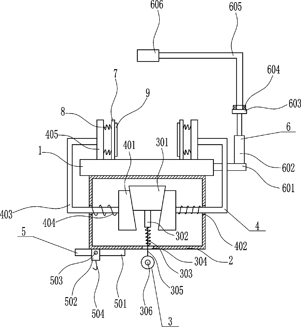
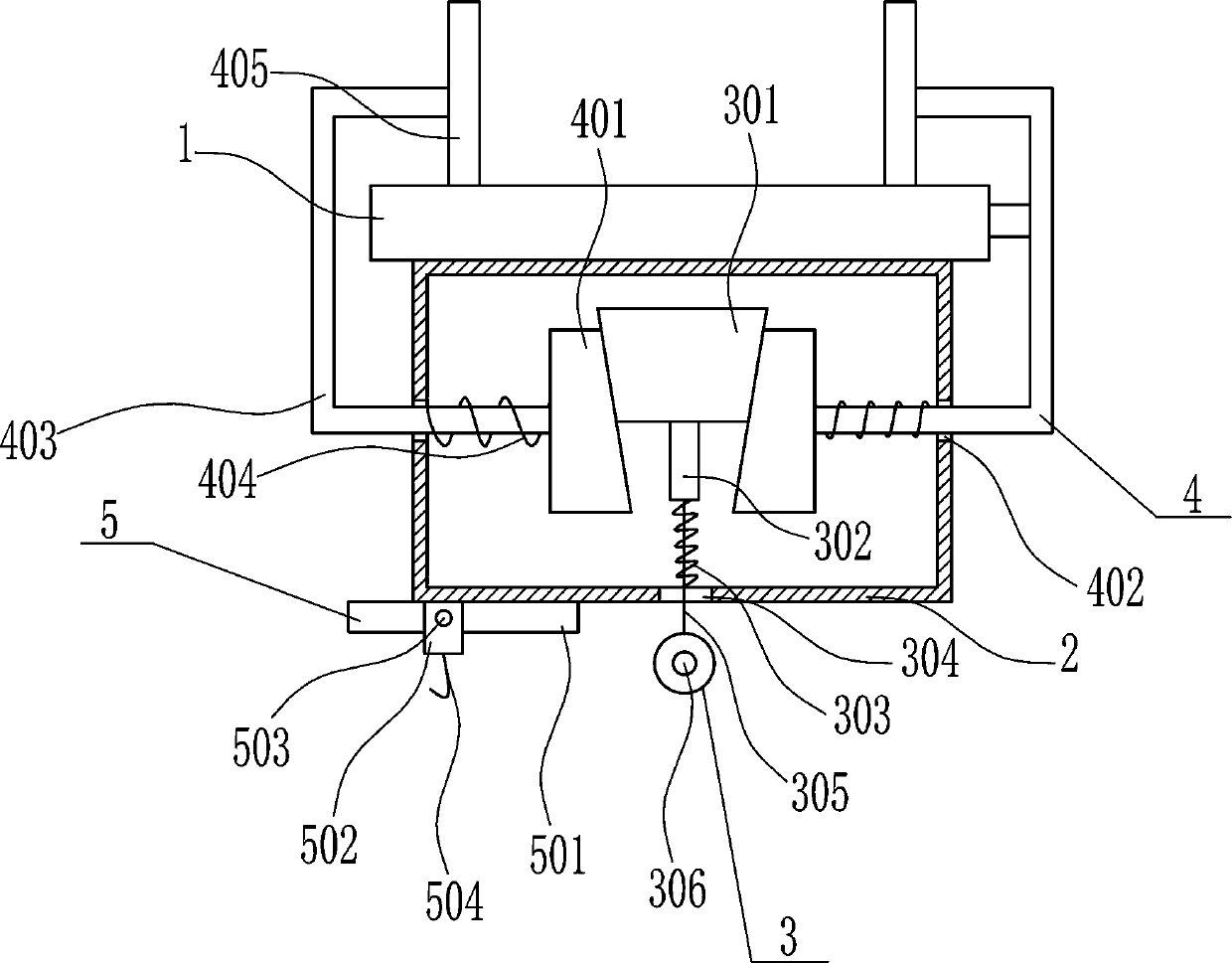
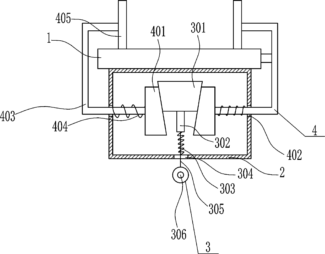
[0035] A head immobilization device for ophthalmic surgery, such as Figure 1-5 As shown, it includes an operating bed 1, a housing 2, a driving mechanism 3 and a fixing mechanism 4. The bottom of the operating bed 1 is provided with a housing 2, the inner bottom of the housing 2 is provided with a driving mechanism 3, and the left and right sides of the housing 2 are provided with The fixed mechanism 4 and the driving mechanism 3 cooperate with the moving parts of the fixed mechanism 4 .

Embodiment 2

[0037] A head immobilization device for ophthalmic surgery, such as Figure 1-5 As shown, it includes an operating bed 1, a housing 2, a driving mechanism 3 and a fixing mechanism 4. The bottom of the operating bed 1 is provided with a housing 2, the inner bottom of the housing 2 is provided with a driving mechanism 3, and the left and right sides of the housing 2 are provided with The fixed mechanism 4 and the driving mechanism 3 cooperate with the moving parts of the fixed mechanism 4 .

[0038]The driving mechanism 3 includes a trapezoidal block 301, a connecting rod 302, a first spring 303, a stay cord 305 and a pull ring 306. The middle of the housing 2 is provided with a trapezoidal block 301, and the bottom of the trapezoidal block 301 is welded with a connecting rod 302. The connecting rod 302 A first spring 303 is connected between the bottom end and the inner bottom of the housing 2 through a hook 504, a first through hole 304 is opened directly below the connecting ...

Embodiment 3

[0040] A head immobilization device for ophthalmic surgery, such as Figure 1-5 As shown, it includes an operating bed 1, a housing 2, a driving mechanism 3 and a fixing mechanism 4. The bottom of the operating bed 1 is provided with a housing 2, the inner bottom of the housing 2 is provided with a driving mechanism 3, and the left and right sides of the housing 2 are provided with The fixed mechanism 4 and the driving mechanism 3 cooperate with the moving parts of the fixed mechanism 4 .

[0041] The driving mechanism 3 includes a trapezoidal block 301, a connecting rod 302, a first spring 303, a stay cord 305 and a pull ring 306. The middle of the housing 2 is provided with a trapezoidal block 301, and the bottom of the trapezoidal block 301 is welded with a connecting rod 302. The connecting rod 302 A first spring 303 is connected between the bottom end and the inner bottom of the housing 2 through a hook 504, a first through hole 304 is opened directly below the connecting...


PUM


Abstract

The invention relates to a fixing device, in particular to a head fixing device for an ophthalmologic operation. The head fixing device for the ophthalmologic operation is good in fixing effect, easyto operate and convenient to use. In order to achieve the technical purposes, the head fixing device for the ophthalmologic operation comprises an operation bed and the like; a shell is arranged at the bottom of the operation bed, a driving mechanism is arranged at the bottom in the shell, fixing mechanisms are arranged on the left side and the right side of the shell, and the driving mechanism ismatched with moving parts of the fixing mechanisms. The head of a patient is fixed through the cooperation of the driving mechanism and the fixing mechanisms; the driving mechanism is fixed through the fixing device, and an operation assisting device is used for observing pathogenetic conditions, so that the effects of being good in fixing effect, easy to operate and convenient to use are achieved.

Description

technical field [0001] The invention relates to a fixing device, in particular to a head fixing device for ophthalmic surgery. Background technique [0002] The full name of ophthalmology is "eye disease specialist", which is a discipline that studies diseases that occur in the visual system, including the eyeball and its associated tissues. Ophthalmology generally studies vitreous, retinal diseases, optometry, glaucoma and optic neuropathy, cataract and other ophthalmic diseases. [0003] The existing head fixation device for ophthalmic surgery has the disadvantages of poor fixation effect, complicated operation and troublesome use. Therefore, it is urgent to develop a head fixation device for ophthalmic surgery with good fixation effect, simple operation and convenient use. Contents of the invention [0004] (1) Technical problems to be solved [0005] In order to overcome the shortcomings of poor fixation effect, complicated operation and troublesome use of the existi...

Claims


Application Information

Patent Timeline
Patent Type & Authority Applications(China)
IPC IPC(8): A61G13/00A61G13/12A61G13/10
CPCA61G13/00A61G13/10A61G13/121A61G2210/00
Inventor 钟文涛蔡庆灵邹久星邱长根
Owner 邱长根
Why Eureka
Try Eureka