Improved power line connection equipment

A technology for accessing equipment and power lines, applied in the direction of circuits, connections, electrical components, etc., can solve problems such as potential safety hazards of power sockets, impact of electrical equipment, and disconnection of power connectors, and achieve the effect of improving the safety of electricity use

Inactive Publication Date: 2018-07-17
广州程科电子科技有限公司
View PDF3 Cites 0 Cited by
  • Summary
  • Abstract
  • Description
  • Claims
  • Application Information

AI Technical Summary

Problems solved by technology

[0002] With the improvement of the application level of power technology, there are more and more types of electrical equipment, which brings great convenience to people. These electrical equipment need to be powered on before they can operate. The pole is inserted into the power connection slot to complete the power supply, but because the power connection slot is generally directly connected to the outside, and the power supply piece extends into the power connection groove, and the power supply piece is directly connected to the mains, so the common metal When the rod is inserted into the power connection slot, it will contact the power supply piece, which will cause an electric shock accident. Therefore, the traditional power connection seat has a great safety hazard, and when the traditional power connection head is matched with the power connection When the kick touches the power connector or kicks the electric wire, it will cause the power connector to fall off, which will cause a sudden power failure of the electrical equipment, which will easily affect the electrical equipment

Method used


Image

  • Improved power line connection equipment
  • Improved power line connection equipment
  • Improved power line connection equipment

Examples


Embodiment Construction

[0023] All features disclosed in this specification, or steps in all methods or processes disclosed, may be combined in any manner, except for mutually exclusive features and / or steps.

[0024] Any feature disclosed in this specification (including any appended claims, abstract and drawings), unless expressly stated otherwise, may be replaced by alternative features which are equivalent or serve a similar purpose. That is, unless expressly stated otherwise, each feature is one example only of a series of equivalent or similar features.

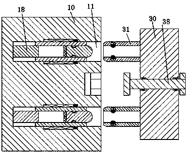
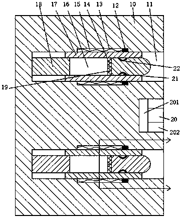
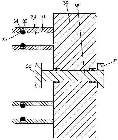
[0025] Such as Figure 1 to Figure 6 As shown, an improved power line access device of the device of the present invention includes a power socket 10 fixedly installed in the wall and a power socket 30 connected to the device, and the power socket 10 is symmetrically provided with openings up and down. Right-facing insertion hole 11, the center of the left end wall of the insertion hole 11 is fixed with a cylindrical rod 18 extending to the r...


PUM


Abstract

The invention discloses improved power line connection equipment. The improved power line connection equipment comprises a power connection seat and a power connection head, wherein the power connection seat is fixedly arranged in a wall, the power connection head is connected with the equipment, insertion holes are vertically and symmetrically formed in the power connection seat and are providedwith rightward openings, a cylindrical rod is fixedly arranged in the center of a left end wall of each insertion hole and extends rightwards, a first through groove is formed in the cylindrical rod,communicates upwards and downwards and extends leftwards and rightwards, arc grooves are vertically and symmetrically formed in the cylindrical rod and communicate with the insertion holes, conductivesheets are fixedly arranged in inner walls of the arc grooves, a sleeve is arranged between the cylindrical rod and the insertion hole and comprises four equal arc plates, the four equal arc plates can independently slide leftwards and rightwards between the cylindrical rod and the insertion hole, a first power connection arm and a second power connection arm are vertically and symmetrically arranged in the first through groove and prop against each other, and the first power connection arm and the second power connection art are respectively and fixedly connected with the arc plate arrangedat an upper end and the arc plate arranged at a lower end.

Description

technical field [0001] The invention relates to the field of power connection of electric equipment, in particular to an improved power line connection equipment. Background technique [0002] With the improvement of the application level of power technology, there are more and more types of electrical equipment, which brings great convenience to people. These electrical equipment need to be powered on before they can operate. The pole is inserted into the power connection slot to complete the power supply, but because the power connection slot is generally directly connected to the outside, and the power supply piece extends into the power connection groove, and the power supply piece is directly connected to the mains, so the common metal When the rod is inserted into the power connection slot, it will contact the power supply piece, which will cause an electric shock accident. Therefore, the traditional power connection seat has a great safety hazard, and when the tradi...

Claims


Application Information

Patent Timeline
Patent Type & Authority Applications(China)
IPC IPC(8): H01R13/447H01R13/453H01R13/639
CPCH01R13/639H01R13/447H01R13/453
Inventor 韦健杭刘建华
Owner 广州程科电子科技有限公司
Why Eureka
Try Eureka