Double-cam driven hole puncher

A puncher and double cam technology, applied in metal processing and other directions, can solve the problems of inconvenient operation, slow running speed of punching head, time-consuming and laborious manual pressing, etc. Effect

Pending Publication Date: 2018-08-24
HUZHOU TEACHERS COLLEGE
View PDF0 Cites 0 Cited by
  • Summary
  • Abstract
  • Description
  • Claims
  • Application Information

AI Technical Summary

Problems solved by technology

[0003] 1. Manual pressing is time-consuming, laborious and inefficient, and because the punch head runs slowly, the edges of the punched holes are rough and irregular;
[0004] 2. Punchers driven by electricity are generally complex in structure, cannot work without power supply, and are inconvenient to operate

Method used


Image

  • Double-cam driven hole puncher
  • Double-cam driven hole puncher
  • Double-cam driven hole puncher

Examples


Embodiment Construction

[0043] The technical solutions in the embodiments of the present invention will be clearly and completely described below in conjunction with the accompanying drawings in the embodiments of the present invention. Obviously, the described embodiments are only some of the embodiments of the present invention, not all of them. Based on the embodiments of the present invention, all other embodiments obtained by persons of ordinary skill in the art without making creative efforts belong to the protection scope of the present invention.

[0044] Embodiments of the present invention will be further described in detail below in conjunction with the accompanying drawings.

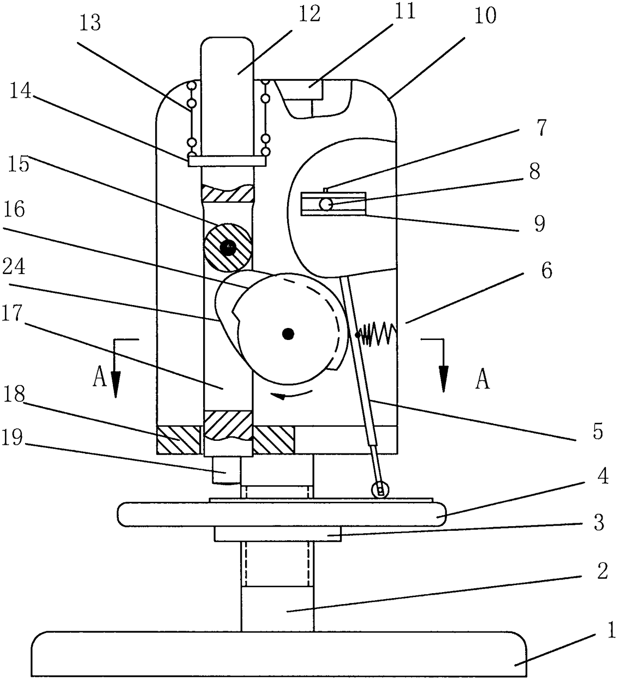
[0045] Such as figure 1 As shown, a double-cam driven hole puncher of the present invention includes a supporting part, a vertical shaft assembly, a driving mechanism, and a transmission mechanism;

[0046] The vertical shaft assembly is installed on the supporting part and passes through the supporting part to co...


PUM


Abstract

The invention discloses a double-cam driven hole puncher which comprises a bearing part, a vertical shaft assembly, a driving mechanism and a transmission mechanism, wherein the vertical shaft assembly is mounted on the bearing part and penetrates through the bearing part to finish axial movement; and the driving mechanism is mounted on the bearing part, is in contact with the vertical shaft assembly and drives corresponding components of the vertical shaft assembly. Through operating the driving mechanism, the rotating motion of the driving mechanism is converted into the up-down reciprocating motion of the vertical shaft assembly; the vertical shaft assembly generates impact force of reciprocating motion and is cooperated with corresponding components of the bearing part to punch an article; the transmission mechanism is linked with the driving mechanism; and when the punching action is finished each time, the driving mechanism drives the transmission mechanism to transmit the to-be-punched article by certain distance, so that automatic feeding and fixed-distance punching are realized.

Description

technical field [0001] The invention relates to a punching device, in particular to a double-cam driven puncher. Background technique [0002] In daily life and work, it is often necessary to punch paper, cardboard, plastic, leather and other items. However, some existing punchers are punched by hand or driven by electricity. There are three problems: [0003] 1. Manual pressing is time-consuming, laborious and inefficient, and because the punch head runs slowly, the edges of the punched holes are rough and irregular; [0004] 2. The general structure of the hole punch driven by electricity is complex, and it cannot work without a power supply, and the operation is also inconvenient. [0005] 3. It cannot be fed automatically to achieve fixed-distance punching. Contents of the invention [0006] The object of the present invention is to provide a fixed-distance puncher with simple structure, time-saving and labor-saving, and adjustable punching distance. [0007] The pu...

Claims


Application Information

Patent Timeline
Patent Type & Authority Applications(China)
IPC IPC(8): B26F1/02B26D7/06B26D5/16B26D7/26
CPCB26F1/02B26D5/16B26D7/06B26D7/2628
Inventor 不公告发明人
Owner HUZHOU TEACHERS COLLEGE
Why Eureka
Try Eureka